R426LS
9 – 2
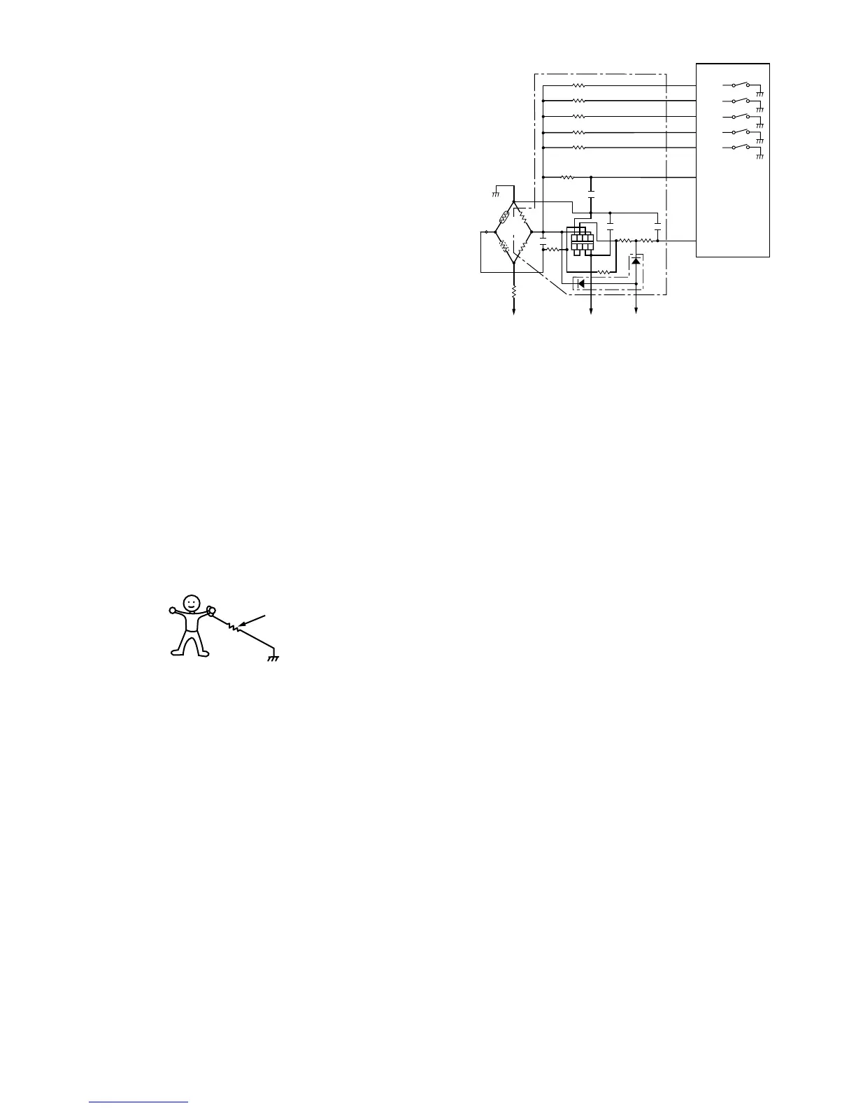
Then the LSI observes that voltage at AN1 terminal and compares it
with its initial value, and when the comparison rate reaches the preset
value (fixed for each menu to be cooked), the LSI causes the unit to
stop sensor cooking; thereafter, the unit goes in the next operationau-
tomatically.When the LSI starts to detect the initial voltage at
AN1terminal 16 seconds after the unit has been put in the Sensor
Cooking mode, if it is not possible to balance the bridge circuit due to
disconnection of the absolute humidity sensor, ERROR will appear on
the display and the cooking is stopped.
1)Absolute humidity sensor circuit
[3] SERVICING FOR TOUCH CONTROL PANEL
1. Precautions for Handling Electronic Components
This unit uses CMOS LSI in the integral part of the circuits. When han-
dling these parts, the following precautions should be strictly followed.
CMOS LSI have extremely high impedance at its input and output ter-
minals. For this reason, it is easily influenced by the surrounding high
voltage power source, static electricity charge in clothes, etc., and
sometimes it is not fully protected by the built-in protection circuit.
In order to protect CMOS LSI.
1) When storing and transporting, thoroughly wrap them in aluminium
foil. Also wrap PW boards containing them in aluminium foil.
2) When soldering, ground the technician as shown in the figure and
use grounded soldering iron and work table.
2. Servicing of Touch Control Panel
We describe the procedures to permit servicing of the touch control
panel of the microwave oven and the precautions you must take when
doing so. To perform the servicing, power to the touch control panel is
available either from the power line of the oven itself or from an exter-
nal power source.
1. Servicing the touch control panel with power supply of the oven:
CAUTION: THE HIGH VOLTAGE TRANSFORMER OF THE MICRO-
WAVE OVEN IS STILL LIVE DURING SERVICING AND
PRESENTS A HAZARD.
Therefore, before checking the performance of the touch control
panel,
1) Disconnect the power supply cord and then remove outer case.
2) Open the door and block it open.
3) Discharge high voltage capacitor.
4) Disconnect the leads to the primary of the power transformer.
5) Ensure that these leads remain isolated from other components
and oven chassis by using insulation tape.
6) After that procedure, re-connect the power supply cord.
After checking the performance of the touch control panel,
1) Disconnect the power supply cord.
2) Open the door and block it open.
3) Re-connect the leads to the primary of the power transformer.
4) Re-install the outer case (cabinet).
5) Re-connect the power supply cord after the outer case is
installed.
6) Run the oven and check all functions.
a) On some models, the power supply cord between the touch
control panel and the oven itself is so short that the two can't
be separated. For those models, check and repair all the
controls (sensor-related ones included) of the touch control
panel while keeping it connected to the oven.
b) On some models, the power supply cord between the touch
control panel and the oven proper is so long enough that
they may be separated from each other. For those models,
therefore, it is possible to check and repair the controls of the
touch control panel while keeping it apart from the oven
proper; in this case you must short both ends of the door
sensing switch (on PWB) of the touch control panel with a
jumper, which brings about an operational state that is equiv-
alent to the oven door being closed. As for the sensor-
related controls of the touch control panel, checking them is
possible if the dummy resistor(s) with resistance equal to
that of the controls are used.
2. Servicing the touch control panel with power supply from an exter-
nal power source:
Disconnect the touch control panel completely from the oven
proper, and short both ends of the door sensing switch (on PWB) of
the touch control panel, which brings about an operational state
that is equivalent to the oven door being closed. Connect an exter-
nal power source to the power input terminal of the touch control
panel, then it is possible to check and repair the controls of the
touch control panel; it is also possible to check the sensor-related
controls of the touch control panel by using the dummy resistor(s).
3. Servicing Tools
Tools required to service the touch control panel assembly.
1) Soldering iron: 60W
(It is recommended to use a soldering iron with a grounding termi-
nal.)
2) Oscilloscope: Single beam, frequency range: DC - 10MHz type or
more advanced model.
3) Others: Hand tools