Do you have a question about the Sharp R-426LS and is the answer not in the manual?
| Brand | Sharp |
|---|---|
| Model | R-426LS |
| Category | Microwave Oven |
| Language | English |
Essential safety steps and checks to perform before initiating any service work on the microwave oven.
Steps to take before starting service, including safety checks and power disconnection.
Procedure for safely concluding tests, including reassembly and final checks.
Steps to follow after completing repairs, ensuring proper reassembly and functionality.
Technical specifications and safety standards for microwave leakage measurement.
Steps and materials needed to prepare the oven and test equipment for leakage testing.
Detailed procedure for conducting a closed-door microwave leakage test for safety compliance.
Introduction to the service manual and its purpose for the Sharp Microwave Oven R-426LS.
General warnings for safe oven operation, focusing on door integrity and component checks.
Specific warnings about high-voltage parts and potential electrical shock hazards during servicing.
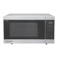
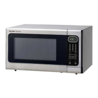
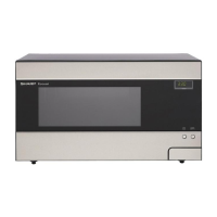
Technical specifications including power, dimensions, and control features of the microwave oven.
Guidelines for proper grounding of the microwave oven to prevent electrical shock.
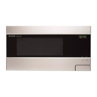
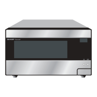
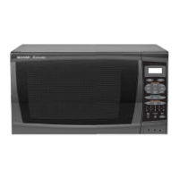
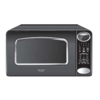
Illustration and identification of major oven parts and the touch control panel.
Explanation of the oven's functional sequence during different operating modes and conditions.
Electrical schematic diagram illustrating the oven's internal circuitry in an off condition.
Detailed explanation of key components like door mechanisms, interlock switches, and control unit.
A chart correlating problems, conditions, and potential defective parts for diagnosis.
Steps to test the magnetron assembly for proper operation and continuity.
Method to test the power transformer's primary and high voltage coil resistance.
Procedure for testing the continuity and resistance of the high voltage rectifier.
Steps to test the high voltage capacitor for shorts or open circuits.
Procedure to check temperature fuses and thermal cut-outs for continuity.
Testing the primary interlock switch for proper operation when the door is opened/closed.
Testing the door sensing switch and secondary interlock relay functionality.
Procedure to test the monitor switch operation in relation to interlock systems.
Steps to diagnose issues related to a blown monitor fuse and associated components.
Method to test the noise filter for continuity and proper function.
Testing the touch control panel assembly, including key unit and control unit.
Specific test procedure for the key unit of the touch control panel.
Procedure to test the operational voltage and continuity of relays RY1 and RY2.
Procedure for testing the defrost function and its operational sequence.
Testing the foil pattern on the PWB, which acts as a fuse, for breaks.
Procedure for testing the Absolute Humidity (AH) sensor and control unit interaction.
Overview of the touch control panel's components, including the Key Unit and Control Unit.
Explanation of the humidity sensor's structure, principle, and detector circuit.
Precautions and procedures for servicing the touch control panel, including component handling.
Information on identifying and using lead-free solder on the main PWB.
Guidelines for using lead-free wire solder, including temperature and bit considerations.
Precautions for soldering with lead-free solder to prevent damage and ensure quality.
Critical safety warnings regarding high voltage and microwave energy exposure during servicing.
Step-by-step instructions for safely removing the oven's outer case.
Procedure for removing and reinstalling the power transformer component.
Steps to safely remove the high voltage rectifier and capacitor.
Procedure for safely removing and reinstalling the magnetron.
Instructions for removing and replacing the oven lamp.
Procedure for disconnecting positive lock connectors.
Steps to remove the entire control panel assembly.
Procedure for replacing the graphic sheet and membrane switch.
Instructions for removing and replacing the turntable motor.
Procedure for removing and replacing the cooling fan motor.
Steps to remove door sensing, primary interlock, and monitor switches.
Procedure for adjusting door interlock switches for proper operation.
Detailed instructions for removing and reinstalling the oven door.
Visual representation of the oven's electrical components and wiring connections.
Detailed circuit diagram for the oven's control panel and associated electronics.
Diagram of the oven's printed wiring board layout and component placement.
List of replacement parts for the main oven assembly, including part numbers.
List of replacement parts for the door and control panel assemblies.