KEi
m
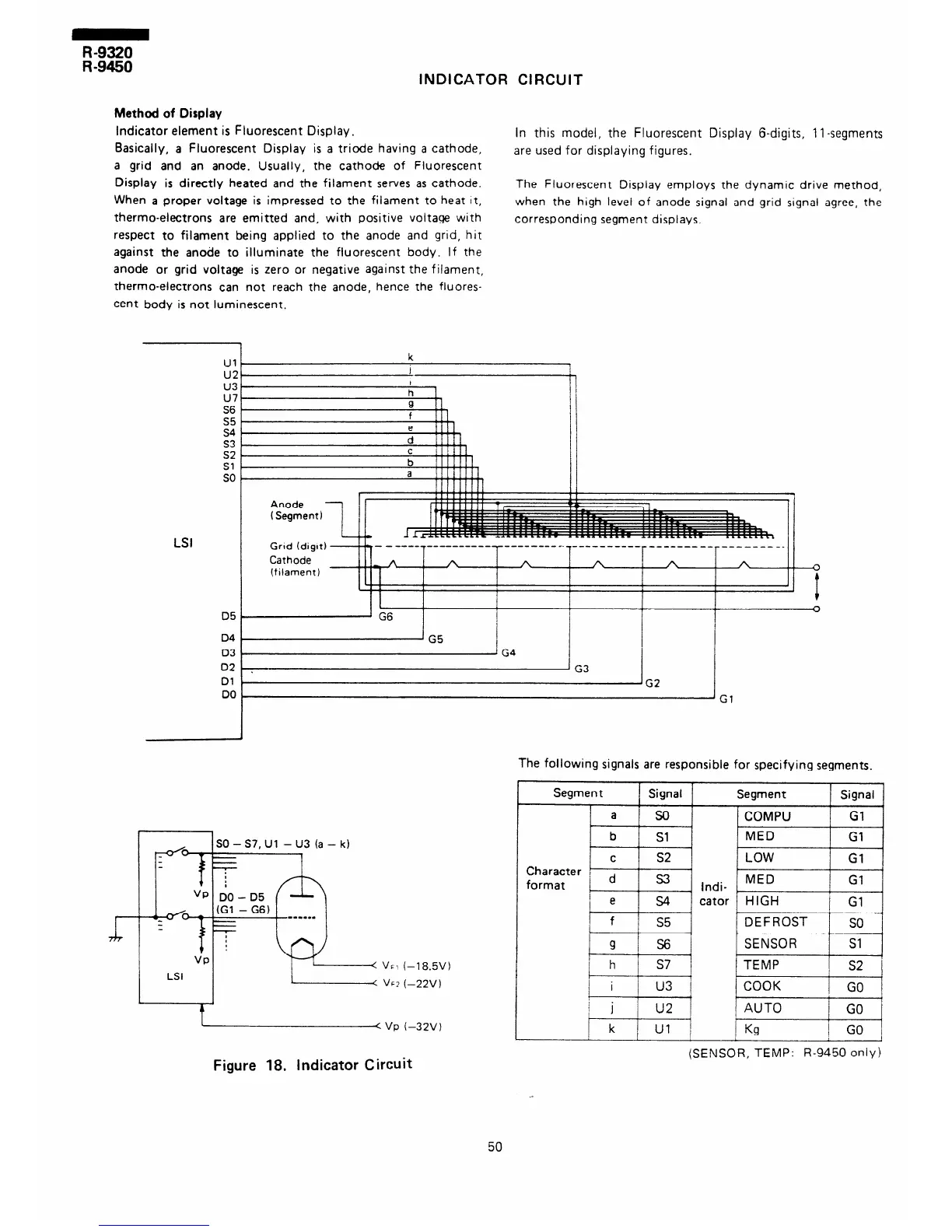
INDICATOR CIRCUIT
Method of Display
Indicator element is Fluorescent Display.
Basically, a Fluorescent Display is a triode having a cathode,
a grid and an anode. Usually, the cathode of Fluorescent
Display is directly heated and the filament serves as cathode.
When a proper voltage is impressed to the filament to heat It,
thermo-electrons are emitted and, with positive voltage with
respect to filament being applied to the anode and grid, hit
against the anode to illuminate the fluorescent body. If the
anode or grid voltage is zero or negative against the fiiament,
thermo-electrons can not reach the anode, hence the fluores-
cent body is not luminescent.
in this model, the Fluorescent Display &digits, 1 l-segments
are used for displaying figures.
The Fluorescent Display employs the dynamic drive method,
when the high level of anode signal and grid signal agree, the
corresponding segment displays.
u7
S6
S5
s4
s3
z:
so
LSI
D5
D4
03
02
01
DO
‘Gi
SO - S7, Ul - U3 (a - k)
i-1 8.5V 1
(-22v 1
C VP i-32V)
The following signals are responsible for specifying segments.
Segment
Signal
Segment Signal
a
so
COMPU
Gl
b
Sl
MED
Gl
C
s2 LOW
Gl
9
s6
h
I S’
i
i
I
/ i u3
+
j
u2
k
! U-l
I
J
DEFROST
so
SENSOR
Sl
TEMP
s2
COOK
GO
AUTO
GO
Kg
1 GO j
Figure 18. Indicator Circuit
(SENSOR, TEMP: R-9450 only)
50