EG
s
SERVICING
1.
Precautions for Handling Electronic Components
This unit uses PMOS LSI in the integral part of the circuits.
When handling these parts, the following precautions
should be strictly followed.
PMOS LSI have extremely high impedance at its input and
output terminals. For this reason, it is easily influenced by
the surrounding high voltage power source, static electricity
charged in clothes, etc, and sometimes it is not fully pro-
tected by the built-in protection circuit.
In order to protect PMOS LSI.
1) When storing and transporting, thoroughly wrap them in
aluminum foil.
Also wrap PW boards containing them In aluminium foil.
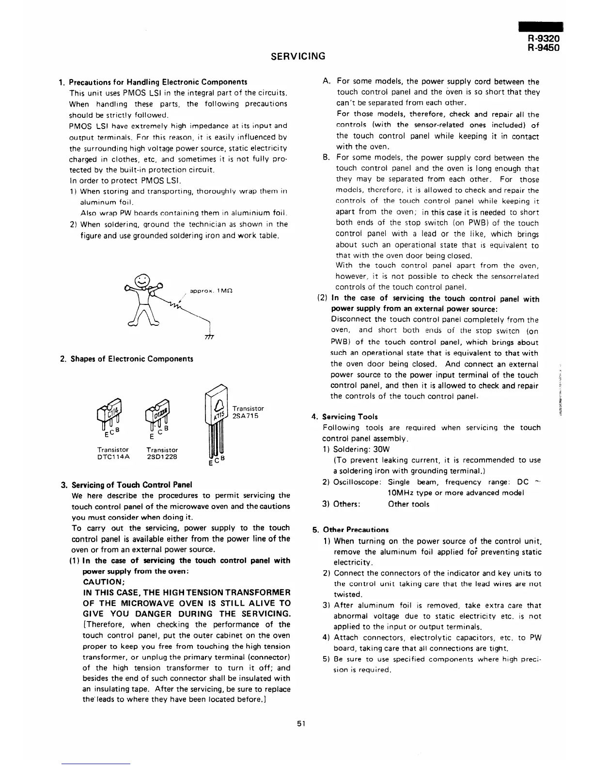
2) When soldering, ground the technician as shown in ?he
figure and use grounded soldering Iron and work table.
. .
, approx.
6
k
R
2. Shapes of Electronic Components
Transistor
DTC114A
Transistor
2SD1228
lMi2
Transistor
2SA715
3. Servicing of Touch Control Panel
We here describe the procedures to permit servicing the
touch control panel of the microwave oven and thecautions
you must consider when doing it.
To carry out the servicing, power supply to the touch
control panel is available either from the power line of the
oven or from an external power source.
(1) In the case of servicing the touch control panel with
power supply from the oven:
CAUTION;
IN THIS CASE, THE HIGH TENSION TRANSFORMER
OF THE MICROWAVE OVEN IS STILL ALIVE TO
GIVE YOU DANGER DURING THE SERVICING.
[Therefore, when checking the performance of the
touch control panel, put the outer cabinet on the oven
proper to keep you free from touching the high tension
transformer, or unplug the primary terminal (connector)
of the high tension transformer to turn it off; and
besides the end of such connector shall be insulated with
an insulating tape. After the servicing, be sure to replace
the’ieads to where they have been located before.]
A. For some models, the power supply cord between the
touch control panel and the &en is so short that they
can’t be separated from each other.
For those models, therefore, check and repair ail the
controls (with the sensor-related ones included) of
the touch control panel while keeping it in contact
with the oven.
6. For some models, the power supply cord between the
touch control panel and the oven is long enough that
they may be separated from each other. For those
models, therefore, it is allowed to check and repair the
controls of the touch control panel while keeping it
apart from the oven;
in this case it is needed to short
both ends of the stop switch (on PWB) of the touch
control panel with a lead or the like, which brings
about such an operational state that rs equivaient to
that with the oven door being closed.
With the touch control panel apart from the oven,
however, it is not possible to check the sensorrelated
controls of the touch control panel.
(2) In the case of servicing the touch control panel with
power supply from an external power source:
Disconnect the touch control panel completely from the
oven,
and short both ends of the stop switch (on
PWB) of the touch control panel, which brings about
such an operational state that is equivalent to that with
the oven door being closed. And connect an external
power source to the power input terminal of the touch
control panel, and then it is allowed to check and repair
the controls of the touch control panel.
4. Servicing Tools
Following tools are required when servicing the touch
control panel assembly .
1) Soldering: 30W
(To prevent leaking current, it is recommended to use
a soldering iron with grounding terminal.)
2) Oscilloscope: Single beam, frequency range: DC -
1 OMHz type or more advanced model
3) Others:
Other tools
5. Other Precautions
1) When turning on the power source of the control unit,
remove the aluminum foil applied foi preventing static
electricity.
2) Connect the connectors of the indicator and key units to
the control unit taking care that the lead wires are not
twisted.
3) After aluminum foil is removed, take extra care that
abnormal voltage due to static electricity etc. is not
applied to the input or output terminals.
4) Attach connectors, electrolytic capacitors, etc. to PW
board, taking care that all connections are tight.
5) Be sure to use specified components where high preci-
sion is required.
51
 Loading...