– 55 –
SD-AT1000H
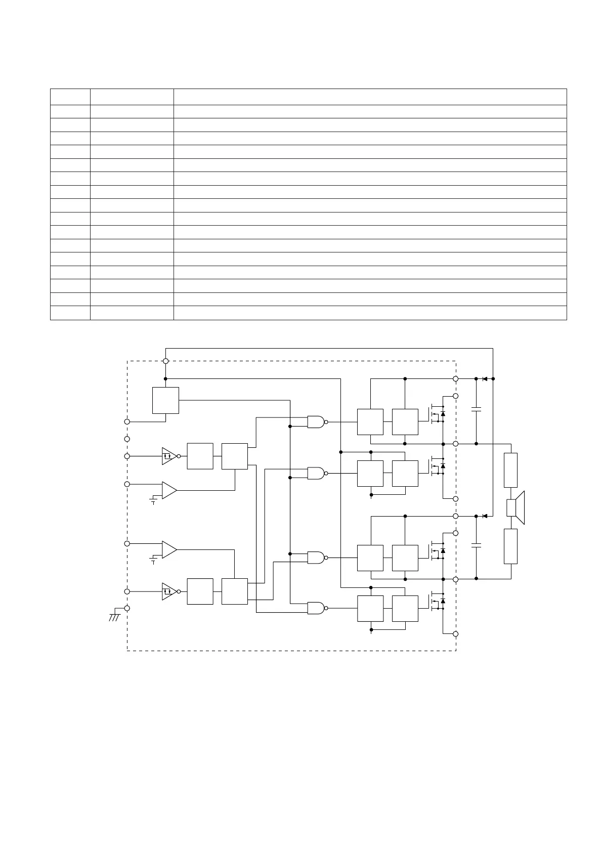
ICA101, ICA102, ICA201, ICA202, ICA301, ICA302
VHiSLA5515M-1: Switching Audio Power Amp. (SLA5515M)
Figure 55 BLOCK DIAGRAM OF IC
Terminal Name
Pin No.
Function
1 SA Output stage low-side source terminal.
2, 3 OUTA Output stage switching output.
4, 5 VBBA Output stage power supply.
6 VBOOTA Bootstrap condenser terminal.
7, 8 DTADJA, DTADJB Dead time adjusting terminal.
9 INA Logic input.
10 VKK Lowest potential terminal of controller.
11 VCC Power supply to pre-driver.
12 VKK Lowest potential terminal of controller.
13 INB Logic input.
14 GND Ground for controller.
15 VDD Power supply to controller.
16 VBOOTB Bootstrap condenser terminal.
17, 18 VBBB Output stage power supply.
19, 20 OUTB Output stage switching output.
21 SB Output stage low-side source terminal.
VKK
VDD
INA
DTADJA
VKK
DTADJB
INB
GND
VCC
UVLO
Level
Down
COCD
Level
Down
COCD
+
-
-
x 4
VKK
+
x 4
Delay
L/S
Driver
VKK
VKK
Delay
L/S
Driver
H/S
Driver
Level
Up
H/S
Driver
Level
Up
ChB_LO
ChB_HO
ChB_LO
ChB_HO
L
P
F
L
P
F
VBOOTA
VBBA
OUTA
SA
VBOOTB
VBBB
OUTB
SB