32
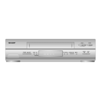
VC-A582U
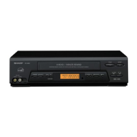
VC-A582U(A)
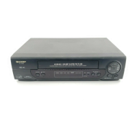
VC-H982U
MTS CIRCUIT ADJUSTMENT.
(HI-FI MODELS ONLY)
5-4 ADJUSTMENT OF SIF-INPUT LEVEL
Measuring AC milli-voltmeter and RF signal
instrument generator.
Mode E-E
Input signal RF CH-10 (at 1kHz 100%MOD.)
Test point AUDIO OUT jack
Control R141(S-IF ADJ.)
Specification –3 ± 2dBs (1.2~2.0Vp-p)
1. Feed the RF signal CH-10 (at 1kHz 100%MOD.) to
antenna terminal.
2. Connect the AC milli-voltmeter to AUDIO OUT jack.
3. Adjust R141(S-IF ADJ.) so that the AC milli-voltmeter
reads –3 ± 2dBs.
5-5 ADJUSTMENT OF FILTER
1. Make the short circuited to TP162 (Sig.)~TP163 (GND).
2. Connect the AC milli-voltmeter to TP168(Sig.)~TP169
(GND).
3. Make a note of the level of TP168 (Sig.)~TP169 (GND).
4. Feed the 15.734kHz at 50mVrms signal to the
TP161(Sig.)~TP163 (GND).
5. Adjust R163 (STEREO VCO ADJ.) so that the levels for
non signal inputed STEP 3. and inputed be just the
same.
6. When the 15.734kHz at 50mVrms signal is fed confirm
the display "STEREO" is indicated on OSD.
5-7 ADJUSTMENT OF STEREO SEPARATION
5-6 ADJUSTMENT OF STEREO VCO
Measuring AC milli-voltmeter
instrument
Mode E-E
Input signal 15.734kHz at 50mVrms
Test point TP168 (Sig.),TP169 (GND)
Control R163 (STEREO VCO ADJ.)
Specification ————————
1. Feed the RF signal CH-10 (300Hz and 3kHz 30%
modulation) to antenna terminal.
2. Connect an Dual AC milli-voltmeter to left channel and
right channel output terminales.
3. Set the audio signal to 300Hz and the modulation factor
to 30% (Left channel only) and adjust R164 (SEPARA-
TION-1 ADJ.) so that the difference between left chan-
nel and right channel outputs becomes maximized.
4. Set the audio signal to 3kHz and the modulation factor
to 30% (right channel only) and adjust R165 (SEPARA-
TION-2 ADJ.) so that the difference between left chan-
nel and right channel outputs becomes maximized.
5. Repeat STEP 3. until obtain a specification.
1. Make the short circuited to TP162 (Sig.)~TP163 (GND).
2. Connect the AC milli-voltmeter to TP164 (Sig.)~TP165
(GND).
3. Feed the 22.9kHz at 245mVrms signal to the
TP161(Sig.)~TP163 (GND).
4. Adjust R163 (FILTER ADJ.) so that the AC milli-voltmeter
reads minimized.
Measuring Dual AC milli-voltmeter and RF
instrument signal generator.
Mode E-E
Input signal RF CH-10 (300Hz and 3kHz 30%
modulation)
Test point AUDIO OUT jack
Control R164 (SEPARATION-1 ADJ.)
R165 (SEPARATION-2 ADJ.)
Specification maximized
Measuring AC milli-voltmeter
instrument
Mode E-E
Input signal 22.9kHz at 245mVrms
Test point TP164 (Sig.),TP165 (GND)
Control R163 (FILTER ADJ.)
Specification Minimized