47
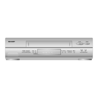
VC-A582U
VC-A582U(A)
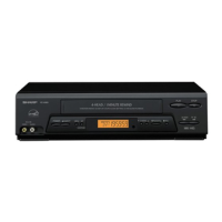
VC-H982U
Playback picture does not appear (E-E mode is possible).
YES
YES
YES
YES
YES
YES
YES
YES
NO
NO
YES
YES
YES
YES
YES
YES
YES
NO
NO
NO
NO
NO
NO
NO
NO
NO
NO
NO
NO
Is V-H.SW.P. applied to the
IC201 pin 81?
Although picture is played back, color does not appear (E-E mode is possible).
Is voltage 5V applied to the CCD section power terminal IC201 pin 36?
Is control voltage approx. 5V applied normally to the pin 37 from the IC201 pin 57? Is CCD clock signal (approx.
7.16 MHz/0.5 Vp-p) applied to the pin 44 from the IC201 pin 69?
Check between the IC201 pin 24 and pin 23. (Check C210.)
Is luminance signal (approx. 0.5
Vp-p) input to the IC201 pin 23?
Is luminance signal (approx. 0.5
Vp-p) input to the IC201 pin 26?
Is luminance signal (approx. 0.5
Vp-p) input to the IC201 pin 42?
Is luminance signal (approx. 0.5
Vp-p) input to the IC201 pin 19?
Is FM signal (approx. 0.4 Vp-p)
input to the IC201 pin 78?
Is luminance signal (approx. 0.4
Vp-p) input to the IC201 pin 79?
Is luminance signal (approx. 0.5
Vp-p) input to the IC201 pin 39?
Check between the IC201 pin 39
and pin 26. (Check C212.)
Check between the IC201 pin 21
and pin 42. (Check C208.)
Check between the IC201 pin 18
and pin 19. (Check C206.)
Check between the IC201 pin 55
and pin 54. (Check C514.)
Check between the IC201 pin 79
and pin 78.
Is the luminance signal (approx. 0.25
Vp-p) input and output to the IC201
pins 13 and 14 and 16, respectively?
Is voltage 5V applied to the chroma
power terminal IC201 pin 61?
Is chroma signal (approx. 403
mVp-p/Burst) input into the
IC201 pin 46?
Is chroma signal (approx. 508
mVp-p/Burst) input into the
IC201 pin 58?
Is chroma signal (approx. 286
mVp-p/Burst) input into the
IC201 pin 54?
Check between the IC201 pin 60
and pin 46. (Check C512.)
Check between the IC201 pin 58
and pin 35. (Check R505, C515.)
Check the periphery of IC201 pin
61 and PC 5V line.
Check the periphery of IC201 pin
13 and 14 and 16. (Check C203,
R201-2, L201, C205, R203.)
Check whether the IC201 pins 71
and 73 oscillate (3.58 MHz)?
Is chroma signal (approx. 508
mVp-p/Burst) output to the IC201
pin 35?
Check V-H.SW.P. line.
Replace IC201.
Replace IC201.
FLOW CHART NO.21 FLOW CHART NO.22