A
B
C
D
E
F
G
H
123456
7 8 9 10 11 12
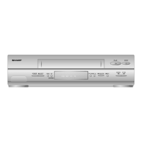
VC-A582U
VC-A582U(A)
VC-H982U
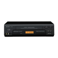
VC-A582U
VC-A582U(A)
VC-H982U
59
60
SCHEMATIC DIAGRAM
IMPORTANT SAFETY NOTICE:
PARTS MARKED WITH "
å
"
( )
ARE
IMPORTANT FOR MAINTAINING THE SAFETY
OF THE SET.
BE SURE TO REPLACE THESE PARTS WITH
SPECIFIED ONES FOR MAINTAINING THE SAFE-
TY AND PERFORMANCE OF THE SET.
• The indicated voltages in the following diagram
are measured with an SSVM, upon receiving
color bars (400 Hz sound signal) in either the
record mode or the play mode voltage is indi-
cated as follows.
4.0
. . . .
Record mode (SP)
(4.0)
. . . .
PB mode (SP)
4.0
. . . .
LP mode
4.0
. . . .
EP mode
NOTE:
1. The unit of resistance "ohm" is omitted (K: 1000
ohms M: 1 Meg ohm).
2. All resistors are 1/8 watt, unless otherwise noted.
3. All capacitors
µ
F, unless otherwise noted P:
µµ
F.
Voltages and waveform are measured as follows:
• DC voltages are measured with an SSVM placed
between points indicated and chassis ground,
with the supply voltage of 120V AC and all
controls for normal positions.
This circuit diagram is a standard one, actual circuits
printed may be subject to change for product
improvement without prior notice.