16
VT-G14
VT-G21
ËË
ËË
Ë
CONVERGENCE ADJUSTMENT
1.CONVERGENCE ADJUSTMENT
(to be done after the purity adjustment)
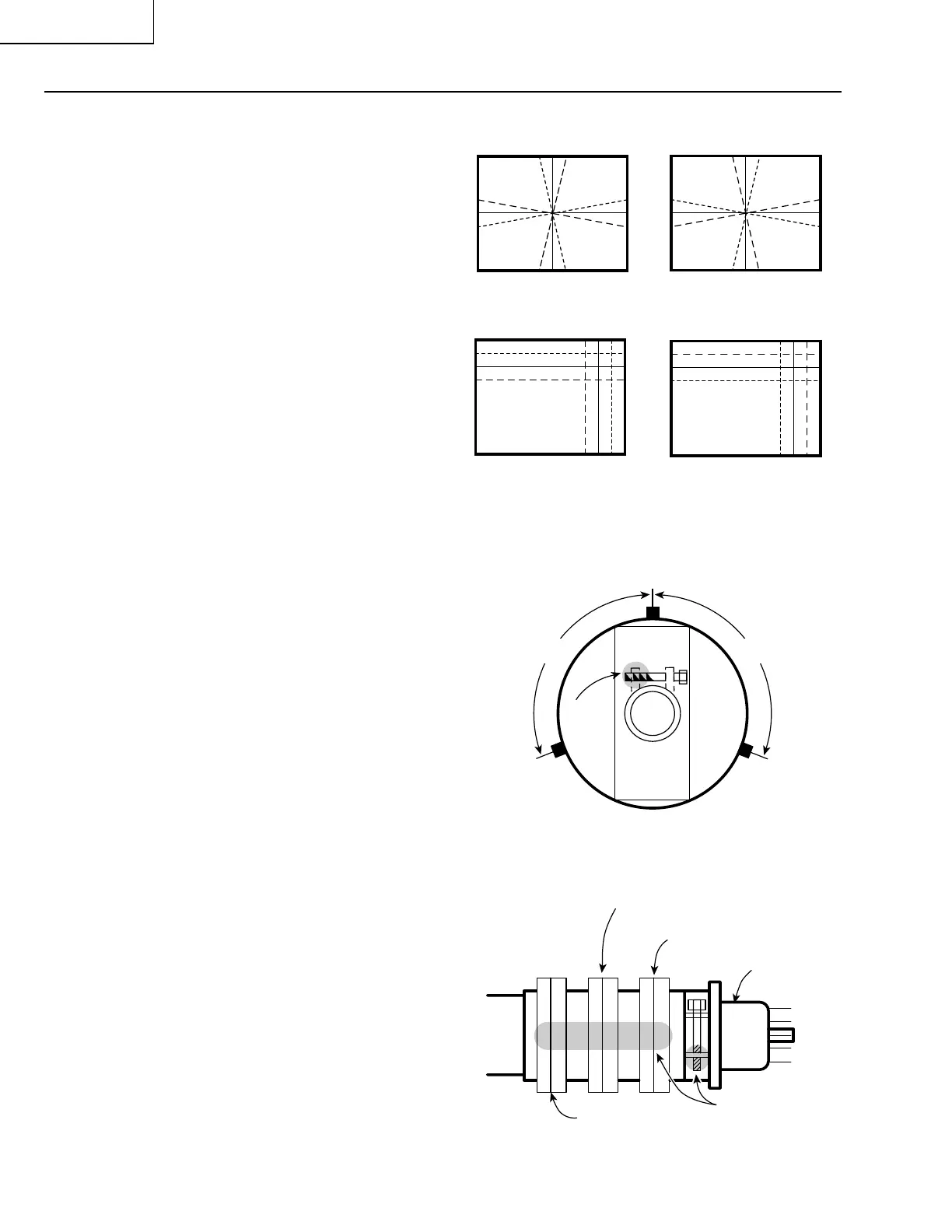
Wedge "a"
Lacquer
Wedge "b" Wedge "c"
Approx.100° Approx.100°
4-pole magnet
6-pole magnet
CRT neck
Lacquer
Purity magnet
1. Receive the crosshatch pattern signal.
2. Using the remote controller, call the Normal mode.
STATIC CONVERGENCE
1. Turn the 4-pole magnet to a proper opening an-
gle in order to superimpose the blue and red col-
ours.
2. Turn the 6-pole magnet to a proper opening an-
gle in order to superimpose the green colour over
the blue and red colours.
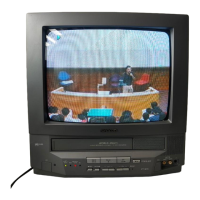
DYNAMIC CONVERGENCE
1. Adjust the convergence on the fringes of the
screen in the following steps.
» Fig. a : Drive the wedge at point “a” and
swing the deflection coil upward.
» Fig. b :Drive the wedges at points “b” and
“c” and swing the deflection coil
downward.
» Fig. c : Drive the “c” wedge deeper and
swing the deflection coil rightward.
» Fig. d :Drive the “d” wedge deeper and
swing the deflection coil leftward.
2. Fix all the wedges on the cathode ray tube and
apply glass tape over them.
3. Apply lacquer to the deflection yoke lock screw,
magnet unit (purity, 4-pole and 6-pole magnets),
and magnet unit lock screw.
Finally receive the red-only and blue-only colour sig-
nals and make sure there is no other colour mixed
on the screen.
Fig. a
Fig. b
Fig. c
Fig. d
Fig. 5
B G R
B
G
R
R G B
B
G
R
R G B
R
G
B
B G R
R
G
B