19
VT-G14
VT-G21
ËË
ËË
Ë
PAL CHROMA ADJUSTMENT
1. SUB-COLOUR ADJUSTMENT (I
2
C bus data adjustment)
1. Receive the PAL colour bar signal.
2. Put the set in the service mode.
3. Select the sub-colour mode (COL).
4. Connect the oscilloscope to TP855 (RED cathode).
(Use a 10 : 1 probe.) (TP852 for VT-G14)
» Range: 20 V/div.
» Sweep time: 20 µsec/div.
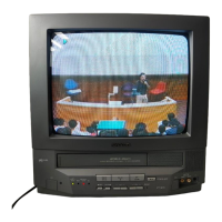
5. Adjust the sub-colour data so that the 75% white
and red portions of the PAL colour bar be at the
same level. See
Fig. 8
.
6. Exit from the service mode.
» When getting out of the SUB-COLOUR mode,
the sub-colour data turns up 15.
W
YCYG
MG
R
B
To be at the same level
Fig.8
ËË
ËË
Ë
SECAM CHROMA ADJUSTMENT
1. BELL FILTER (ƒ0) (I
2
C bus data adjustment ) (adjustment not required)
1. Receive the SECAM colour bar signal.
2. Put the set in the service mode.
3. Select the BELL FILTER (f0) mode (BELL).
4. Adjust the data to 1.
5. Exit from the service mode.
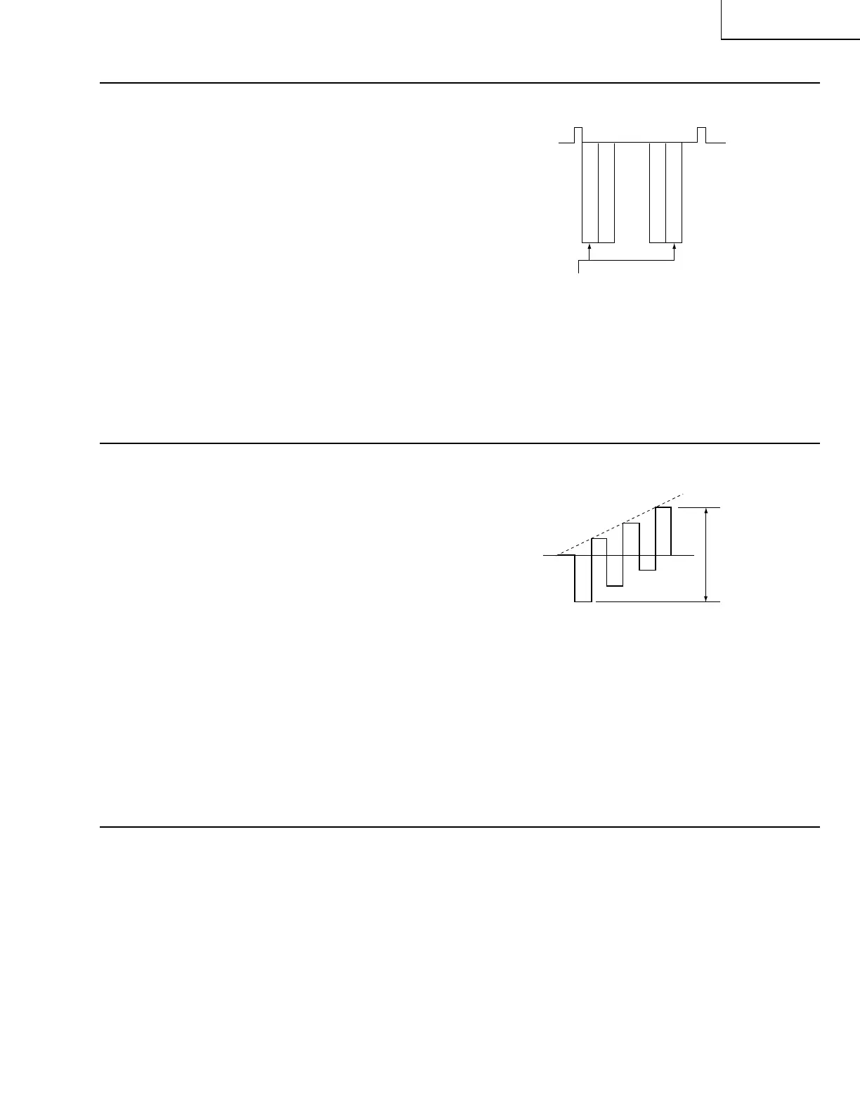
W
Y
CY
G
MG
R
B
About 3 Vp-p
Fig.9
ËË
ËË
Ë
NTSC CHROMA ADJUSTMENT
1. SUB-TINT ADJUSTMENT (I
2
C bus data adjustment)
1. Receive the NTSC colour bar signal.
2. Put the set in the service mode.
3. Select the SUB-TINT mode (TINT).
4. Connect the oscilloscope to TP802 (B-Y OUT).
» Range : 10 mV/div. (AC)
» Sweep time :10 µsec/div.
(Use a 10 : 1 probe.)
5. Adjust the sub-tint data to obtain the waveform
as shown in
Fig. 9
.
6. Exit from the service mode.