43
VT-G14
VT-G21
(Bottom side of mechanism chassis)
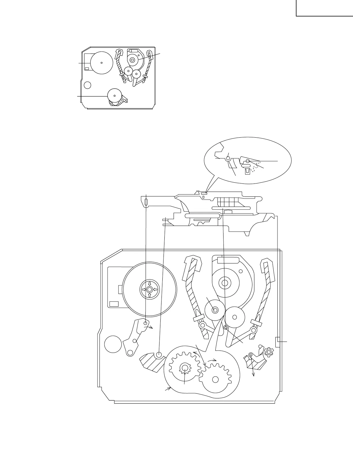
1. Make sure that the loading gear is at the phase-
matching point 1 as shown below.
2. Install, paying attention to 5 insertion points and 3
release points.
3. For the phase matching at the insertion point 1, see
the phase-matching point 2 as shown below.
4. Finally fix the inserts 1 and 4.
Figure 1-43.
INSTALLING THE SHIFTER
Capstan
D.D. motor
Drum
Reel pulley
Figure 1-42.
Phase-Matching
point 2
Loading gear(T)
Half round notch
Round mark
Insert
point 1
Shaft 1
Sifter
Insert
point 3
Insert
point 2
Insert
point 4
Insert
point 5
Rotation
point 2
Release
point 3
Phase-matching
point 1
Shaft 2
Shaft 1
Shaft 1