WQ-740W/WQ-780W
NOTES ON SCHEMATIC DIAGRAM
• Resistor:
To differentiate the units of resistors, The symbol as K and
M are used: the symbol K means 1000 ohm and the symbol
M means 1000 kohm and the resistor without any symbol
is an ohm resistor. The resistor designated “Fusible” is a
fuse type resistor.
• Capacitor:
To indicate the unit of capacitor, a symbol P is used: this
symbol P means pico-farad and the unit of the capacitor
without such a symbol is microfarad. As to electrolytic
capacitor, the expression “capacitance/withstand voltage”
is used.
(CH),(RH),(UJ): Temperature compensation
(ML): Mylar type
(S): Styrol type
• The indicated voltage in each section is the one measured
by Digital Multimeter between such a section and the
chassis with no signal given.
• Schematic diagram and Wiring Side of P.W. Board for this
model are subject to change for improvement without prior
notice.
• Parts marked with “ ” ( ) are important for
maintaining the safety of the set. Be sure to replace these
parts with specified ones for maintaining the safety and
performance of the set.
REF. NO. DESCRIPTION
SW201 BAND SELECTOR FM
SW301 BEAT CANCEL C
SW302 RECORD/PLAYBACK PLAYBACK
SW401 SURROUND MODE LIVE
SELECT
SW402 SURROUND ON/OFF OFF
SW403 DUBBING SPEED/ HIGH/FM STEREO
BUILT-IN MICROPHONE/
FM MODE
SW404 FUNCTION SELECTOR TAPE
SW501 TAPE 2 MAIN OFF
SW502 TAPE 1 MAIN OFF
SW503 TAPE 2 PLAY OFF
SW504 TAPE 2 DIRECTION A
(WQ-780W Only)
SW505 VOLTAGE SELECTOR AC220-240V
POSITION
– 6 –
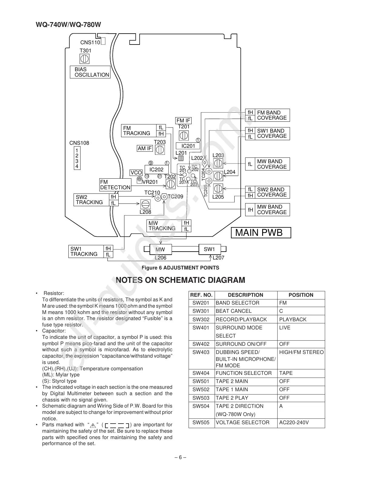
Figure 6 ADJUSTMENT POINTS
FM
TRACKING
fL
fH
AM IF
FM IF
IC201
IC202
FM
DETECTION
VCO
MW
TRACKING
fH
fL
fH
SW1
TRACKING
fH
fL
fH
fL
SW2
TRACKING
fL
fH
fL
fH
fL
fH
fL
FM BAND
COVERAGE
SW1 BAND
COVERAGE
MW BAND
COVERAGE
SW2 BAND
COVERAGE
MW BAND
COVERAGE
CNS110
BIAS
OSCILLATION
T201
L201
L205
L204
L203
L202
TC
202
TC
201
T203
1
19
2113
T202
TC
207
TC
203
TC209
TC210
L208
MW
SW1
L206
L207
TC204
TC205
VR201
CNS108
1
2
3
4
MAIN PWB
T301