-3
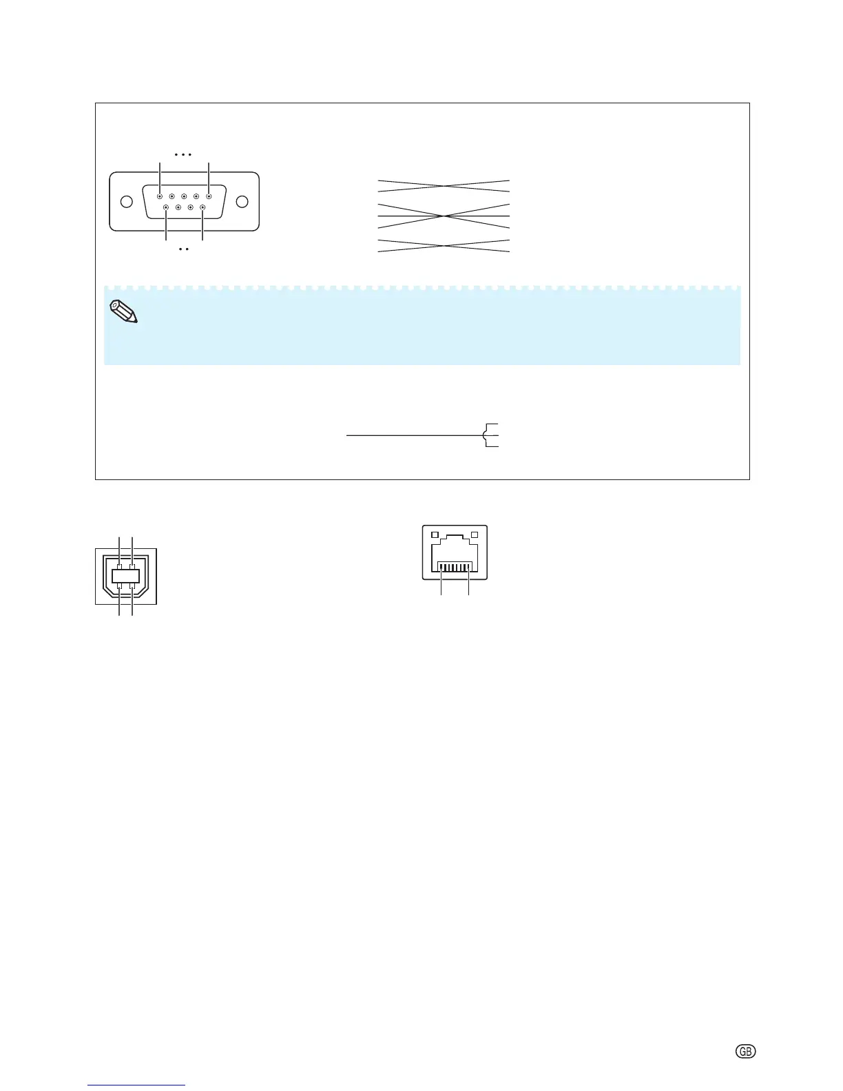
RS-232C Cable recommended connection: D-sub 9 pin female connector
Pin No. Signal Pin No. Signal
1.
2.
3.
4.
5.
6.
7.
8.
9.
CD
RD
SD
ER
SG
DR
RS
CS
CI
1.
2.
3.
4.
5.
6.
7.
8.
9.
CD
RD
SD
ER
SG
DR
RS
CS
CI
Projector
Pin No.
Computer
Pin No.
4
5
6
4
5
6
USB Terminal: Type B USB connector LAN Terminal: LAN (RJ-45)
Pin No. Signal Name Pin No. Signal Pin No. Signal
1.
2.
3.
4.
VCC
USB–
USB+
SG
USB power
USB data–
USB data+
Signal Ground
1.
2.
3.
4.
TX+
TX–
RX+
5.
6.
7.
8.
RX–
51
96
51
96
Depending on the controlling device used, it may be necessary to connect Pin 4 and Pin 6 on the
controlling device (e.g. computer).
•
Note
Depending on the controlling device used, it may be necessary to connect Pin 4 and Pin 6 on the
controlling device (e.g. computer).
•
Note
43
12
43
12
8
...
18
...
1
Connecting Pin Assignments
 Loading...