SAFETY PRECAUTION
IMPORTANT SERVICE SAFETY NOTES
.............i
Precautions for using lead-free solder ..............vi
CHAPTER 1. OPERATION MANUAL
[1] SPECIFICATIONS ......................................... 1-1
[2] Operation Manual........................................... 1-2
[3] DIMENSIONS ................................................ 1-9
[4] Maintenance Indicators................................ 1-10
[5] Regarding the Lamp..................................... 1-12
CHAPTER 2. REMOVING OF MAJOR PARTS
[1]
Removing the Lamp Unit
................................ 2-1
[2] Removing the Top Cover................................ 2-2
[3] Removing the Lens Hood............................... 2-3
[4] Removing the Lens Cap................................. 2-3
[5] Removing the Lens Trim ................................ 2-4
[6] Removing the Standard Lens......................... 2-4
[7] Removing the Top Cabinet............................. 2-5
[8] Removing the Handle Bracket3 ..................... 2-6
[9] Removing the PWB Units............................... 2-7
[10]
Removing the Optical Engine and Lens Shift
........ 2-8
[11] Removing the Terminal Unit......................... 2-10
[12] Removing the Filter Unit............................... 2-11
[13] Removing the IR (Rear) Unit........................ 2-11
[14]
Removing the Power Unit and Audio Unit
........ 2-12
CHAPTER 3. ELECTRICAL ADJUSTMENT
[1] ELECTRICAL ADJUSTMENT........................ 3-1
[2] PC I/F adjustment method ............................. 3-3
[3] Special 232c command for factory ................. 3-4
[4] SERVICE MODE............................................ 3-5
[5] Failure mode when the lamp does not light
up even when powered on............................. 3-7
CHAPTER 4. TROUBLESHOOTING TABLE
[1] TROUBLESHOOTING TABLE ......................4-1
CHAPTER 5. BLOCK DIAGRAM/OVERALL WIRING
DIAGRAM
[1] BLOCK DIAGRAM.........................................5-1
[2] OVERALL WIRING DIAGRAM......................5-3
CHAPTER 6. PRINTED WIRING BOARD
[1] MAIN Unit ......................................................6-1
[2] FORMATTER Unit .........................................6-5
[3] POWER Unit..................................................6-7
[4] FILTER/P.F.C CONTROL/LVPS CON-
TROL Unit......................................................6-9
[5] PC I/F Unit ................................................... 6-11
[6] DIRECT OFF Unit........................................6-13
[7] AUDIO Unit..................................................6-14
[8] KEYPAD Unit...............................................6-15
[9] TERMINAL Unit ...........................................6-17
[10] IR (FRONT)/IR (REAR)/LAMP1 COVER/
LAMP2 COVER Unit/INDEX Unit ................6-18
CHAPTER 7. WAVEFORMS
[1] WAVEFORMS ...............................................7-1
CHAPTER 8. SCHEMATIC DIAGRAM
[1] DESCRIPTION OF SCHEMATIC DIA-
GRAM............................................................8-1
[2] SCHEMATIC DIAGRAM................................8-2
Parts Guide
SERVICE MANUAL
CONTENTS
Parts marked with " " are important for maintaining the safety of the set. Be sure to replace these parts with specified ones for maintaining the
safety and performance of the set.
This document has been published to be used for
after sales service only.
The contents are subject to change without notice.
TopPage
In the interests of user-safety (Required by safety regulations in some countries) the set should be restored to its orig-
inal condition and only parts identical to those specified should be used.
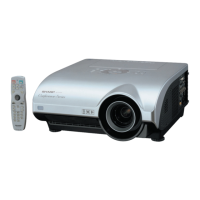
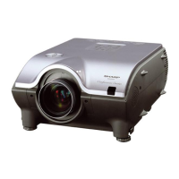
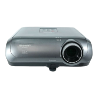
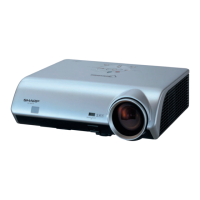
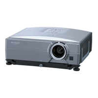
MULTIMEDIA PROJECTOR
XG-PH70X/XG-PH70X-N (1st. Edition)
No. SX6Z1XGPH70X/
XG-PH70X
XG-PH70X-N
MODELS