– 7 –
XL-40H/50H
TAPE MECHANISM SECTION
Perform steps 1 to 7 and 9 of the disassembly method to
remove the tape mechanism. (See page 6.)
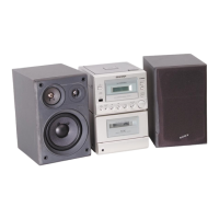
How to remove the record / playback and erase
heads (See Fig. 7-2.)
1. Remove the screws (A1) x 2 pcs., to remove the erase
head.
2. Remove the screws (A2) x 2 pcs., to remove the record/
playback head.
Note:
After replacing the heads and performing the azimuth
adjustment, be sure to apply screwlock.
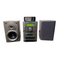
How to remove the pinch roller (See Fig. 7-3.)
1. Carefully bend the pinch roller pawl in the direction of the
arrow <A>, and remove the pinch roller (B1) x 1 pc.,
upwards.
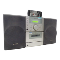
How to remove the belts (See Fig. 7-4.)
1. Remove the main belt (C1) x 1 pc., from the motor pulley.
2. Remove the FF/REW belt (C2) x 1 pc., from the REW/FF
roller.
3. Put on the belts in the reverse order of removal.
Note:
When putting on the belt, ascertain that the belt is not twisted,
and clean it.
How to remove the motor
(See Figs. 7-5.)
1. Remove the mainbelt.
2. Remove the screws (D1) x 2 pcs., to remove the motor
bracket.
3. Remove the screws (D2) x 3 pcs., to remove the motor.
Note:
When mounting the motor, pay attention to the motor mounting
angle
Figure 7-2
Figure 7-3
Figure 7-4
Figure 7-5
<A>
Pinch Roller
(B1)x1
Pinch Roller
Pawl
REMOVING AND REINSTALLING THE MAIN PARTS
Main Belt
(C1)x1
FF/REW Belt
(C2)x1
REW/FF
Clutch
Motor
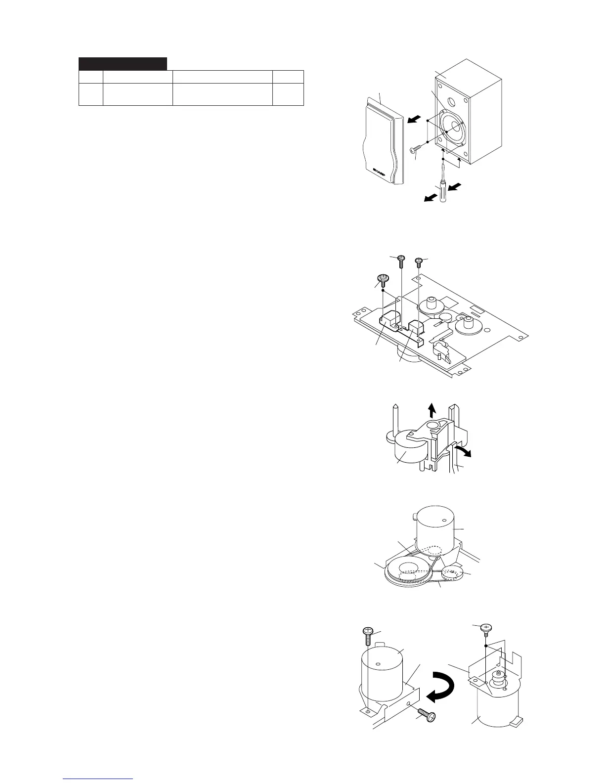
1 Speaker 1. Front panel .......... (A1) x1 7-1
2. Screw .................. (A2) x4
STEP REMOVAL
PROCEDURE
FIGURE
CP-XL40H/50H
Figure 7-1
(A2)x4
ø4x12mm
(A1x1)
Woofer
Speaker Box
Driver
Direction of handle
Driver should be
pried away from
speaker Box.
Erase Head
Record/
Playback Head
(A1)x2
ø2x8mm
(A2)x1
ø2x3mm
(A2)x1
ø2x7mm
(D1)x1
ø2x4mm
(D2)x3
Special
Screw
Motor
Bracket
Motor
Motor
(D1)x1
ø2x4mm