Do you have a question about the Shimadzu MUX-100DJ and is the answer not in the manual?
Safety precautions and meaning of warning symbols.
Detailed instructions for assembling the CXDI-50G component with the unit.
Steps for installing the CXDI control software on the PC.
Configuration steps for the CXDI system, including serial number input.
Configuration process for the CXDI generator communication software.
Procedures for calibrating the unit, including aging steps.
Detailed checks for various unit components like tube current and movement.
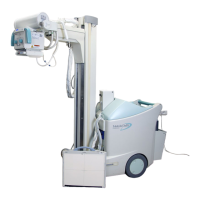
Detailed technical specifications of the MUX-100D and MUX-100DJ units.
Charts and tables detailing valid exposure parameter combinations.
A comprehensive table detailing the function of each NEXSC board DIP switch.
Detailed procedures for calibrating the tube current output.
Steps to adjust and calibrate the battery voltage monitoring circuit.
A comprehensive list of error codes and their meanings for troubleshooting.
| Type | Digital Radiography System |
|---|---|
| Detector Type | Flat Panel Detector (FPD) |
| Image Matrix | 3072 x 3072 |
| Dynamic Range | 16-bit |
| Detector Size | 17" x 17" |
| Pixel Size | 139 μm |
| Power Supply | AC 200-240V, 50/60Hz |
| Dimensions | Varies depending on configuration; refer to installation manual |
| Weight | Varies depending on configuration; refer to installation manual |
| X-Ray Tube Support | Ceiling-mounted |