Do you have a question about the Shimano ST-6510 and is the answer not in the manual?
| Model | ST-6510 |
|---|---|
| Series | Ultegra |
| Category | Bicycle Accessories |
| Speed | 9-speed |
| Compatibility | Shimano Road |
| Brake Compatibility | Caliper |
| Material | Aluminum |
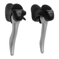
| Color | Silver |
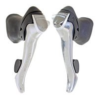
Explains lever A for shifting to larger sprockets and lever B for smaller sprockets, with click stop positions.
Warns against applying pressure to both levers simultaneously to avoid improper gear shifting.
Describes adjusting the front derailleur to prevent chain rub noise on the smaller chainring.
Advises against pressing both front derailleur levers simultaneously to avoid shifting issues.
Details securing the shift/brake lever assembly to the handlebar using an Allen key.
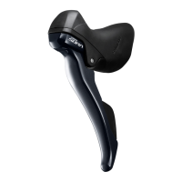
Guides through routing the brake cable through the lever body and outer casing.
Explains how to insert the inner cable into the outer casing with proper greasing for efficiency.
Describes how to cut the outer casing and prepare the end for optimal performance.
Details removing the sensor cap and lever stud set screw to detach the lever from the bracket.
Guides on disassembling the cable hook and the lever/bearing assembly using special tools.
Explains reassembling the bracket and lever, including spring placement and lever stud alignment.
Instructions on how to correctly fit the bracket cover onto the lever assembly.