3-2. Mounting
(1) Machine the mounting hole by referring to the panel-cut illustration in Section 3-3.
(2) Applicable thickness of the mounting panel is 1.2 ~ 2.8mm.
(3) As this product provides mounting fixture, insert the product into the panel.
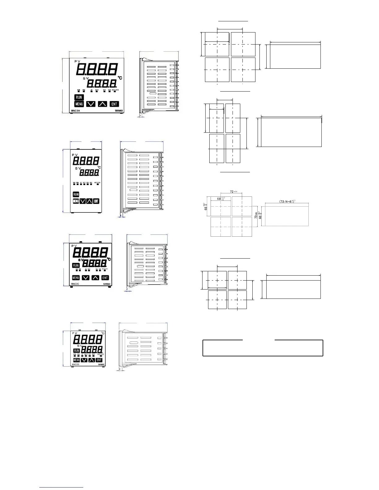
3-3. External dimension and panel cutout
MAC3 external dimensions (unit: mm)
MAC3 panel cutout (unit: mm)
MAC3A 96×96size
92
+0 .8
-0
92
+0 . 8
-0
(9 6 ×N-4)
+0 . 8
-0
96 以 上
92
+0 . 8
-0
96 以 上
In the case ofhorizontal proximityattachment by asingle hole
N:
Number
MAC3B 48×96size
48 以 上
96 以 上
9 2
+0. 8
-0
45
+0. 6
-0
(48 ×N -3)
+0. 6
-0
92
+0 .8
-0
In thecaseof horizontal proximity attachment by asinglehole
N:
Number
MAC3C 72×72size
MAC3D 48×48size
45
+0 .6
-0
45
+0 .6
-0
4 8 以 上
( 4 8 ×N -3)
+0 .6
-0
45
+ 0. 6
- 0
48 以 上
Inthecase of horizontalproximityattachment by asinglehole
N:
Number
Note: Proximity attachment by a single hole is possible only in the case of horizontal direction.
When an apparatus that was attached in vertical direction is removed, a dedicated detachment
tool is required.
3-4.
3-4.3-4.
3-4.Wiring
「
「「
「
WARNING」
」」
」
◎Do not turn on electricity while wiring to avoid an electric shock.
◎Do not touch a terminal or live part while turning on electricity.
(1) Make sure that wiring operation is properly done in line with a terminal wire diagram of section 3-5.
(2) Choose a suitable compensation lead wire in the case of thermocouple input.
(3) In the case of resistance bulb input, resistance value of each lead wire must be less than
5Ω and that of three lead wires must be equal.
(4) Do not wires an input signal line inside of an electric wire pipe or a duct same with the
high voltage line.
(5) Shield wiring (single point grounding) is effective against static induction noise.
(6) Wiring twisted at equal short intervals is effective against electromagnetic induction noise.
 Loading...