2
22
2
Preface
PrefacePreface
Preface
This instruction manual is intended for those who will be involved in wiring,
installation, operation and routine maintenance of the MAC5.
This manual describes the care, installation, wiring, function, and proper
procedures regarding the operation of MAC5.
Keep this manual on hand while using this device. Please follow the provided
guidance.
1.Matters regarding safety
For matters regarding safety, potential damage to equipment and/or facilities
and additional instructions are indicated as follows:
◎This mark indicates hazardous conditions that could cause injury or death
of personnel. Exercise extreme caution as indicated.
「
「「
「
WARNING」
」」
」
◎This mark indicates hazardous conditions that could cause damage to
equipment and/or facilities. Exercise extreme caution as indicated.
「
「 「
「
CAUTION」
」」
」
◎This mark indicates additional instructions and/or notes.
「NOTE」
「
「 「
「
WARNING」
」」
」
MAC5 is designed for controlling temperature, humidity, and other physical
subjects in general industrial facilities. It must not be used in any way that
may adversely affect safety, health, or working conditions.
「
「 「
「
CAUTION」
」」
」
To avoid damage to the connected equipment, facilities or the product itself
due to a fault of this instrument, safety countermeasures must be taken
before usage, such as proper installation of the fuse and the overheating
protection device. No warranty, expressed or implied, is valid in the case of
usage without having implemented proper safety countermeasures.
The mark on the plate affixed to the instrument:
On the terminal nameplate affixed to the case of your instrument, the
mark is printed. This is to warn you of the risk of electrical shock which may
result if the charger is touched while it is energized.
The external power circuit connected to the power terminal of this instrument
must have a means of turning off the power, such as a switch or breaker.
Install the switch or breaker adjacent to the instrument in a position which
allows it to be operated with ease, and with an indication that it is a means of
turning off the power. Use a switch or breaker, which meets the
requirements of IEC127.
Fuse:Since the instrument does not have a built-in fuse, do not forget to
install a fuse in the power circuit to be connected to the power terminal. The
fuse should be positioned between the switch or breaker and the instrument
and should be attached to the L side of the power terminal.
Fuse Rating: 250V AC 0.5A/medium lagged or lagged type.
Use a fuse which meets the requirements of IEC127
Load voltage/current to be connected to the output terminal and the alarm
terminal should be within the rated range. Otherwise, the temperature will rise
and shorten the life of the product and/or result in problems with the product.
lVoltage/current that differs from input specification should not be connected
to the input terminal. It may shorten the life of the product and/or result in
problems with the product.
Input, output of voltage pulse, and output of electric current are not insulated.
Therefore, do not ground an adjusted power terminal when a ground sensor is
employed.
A signal wire's common mode voltage to ground (signal wires other than
contact output including power supply and event) should be less than 30V
rms, 42.4V peak, and 60 VDC .
「
「 「
「
CAUTION」
」」
」
All the wires for the interior distribution, except for communication and
contact output (including power supply and event), should be less than 30m in
length. When the wire's length is 30m or more, or in the case of outdoor
wiring,
the suitable measure against a lightning surge is required.
EMC standard (IEC61326) classifies MAC5 into Class A apparatus.
Electromagnetic interference may occur when MAC5 is used at a business
district or in the home. Please use after taking sufficient measures.
2.Introduction
2.Introduction2.Introduction
2.Introduction
2
22
2-
--
-1. Check before use
1. Check before use1. Check before use
1. Check before use
Before using MAC5, please check the model code, the exterior appearance and
accessories. Also, make sure that there are no errors, impairs and shortages.
Confirmation of model code: Check that the product you ordered is being
delivered properly. Check the model code of the main body case against the
following code table.
Example of model code
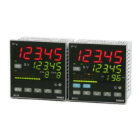
1. Series MAC5A-:96×96mm size digital controller
MAC5B-:48×96mm size digital controller
MAC5C-:72×72mm size digital controller
MAC5D-:48×48mm size digital controller
2. Input M:multi,
3. Control Output 1 C:contact, S:voltage pulse, I:current(4~20mA)
4. Power Supply F-:90 - 264V AC,
5. Event Output E:Event Output1・2 (two points)
6. Control Output 2・Event Output・Optional Selection
N-:none, C-:contact, S-:voltage pulse, E-:Event out
D-Digital input one point
2
22
2-
--
-2. Caution for use
2. Caution for use2. Caution for use
2. Caution for use
(1) Do not operate the front panel keys with hard or sharp objects.
Do not fail to touch keys lightly with a fingertip.
(2) Wipe gently with a dry rag and avoid using solvents such as
thinner.
3. Installation and wiring
3. Installation and wiring3. Installation and wiring
3. Installation and wiring
3
33
3-
--
-1. Installation site (environmental conditions)
1. Installation site (environmental conditions)1. Installation site (environmental conditions)
1. Installation site (environmental conditions)
「CAUTION」
Do not use this product under the following conditions.
Otherwise, failure, damage and fire may occur.
(1) Where flammable gas, corrosive gas, oil mist or dust generate or grow rife.
(2) Where the temperature is below -10℃ or above 55℃.
(3) Where the humidity is over 90%RH or where condensation occurs.
(4) Where high vibration or impact occurs
(5) Where inductive interference may easily affect the operation.
Or, in the region of strong electric circuit area.
(6) Where water drops or direct sunlight exists.
(7) Where the altitude is above 2,000m.
「
NOTE」: The environmental conditions comply with the IEC664.
Installation category isⅡ and the pollution degree is 2.
3
33
3-
--
-2. Mounting
2. Mounting2. Mounting
2. Mounting
(1) Machine the mounting hole by referring to the panel-cut illustration in
Section 3-3.
(2) Applicable thickness of the mounting panel is 1.2 ~ 2.8mm.
(3) As this product provides mounting fixture, insert the product into the panel.
「NOTE」:
MAC 3 is a panel set-up type.
Please use the product after setting up to the panel.
3
33
3-
--
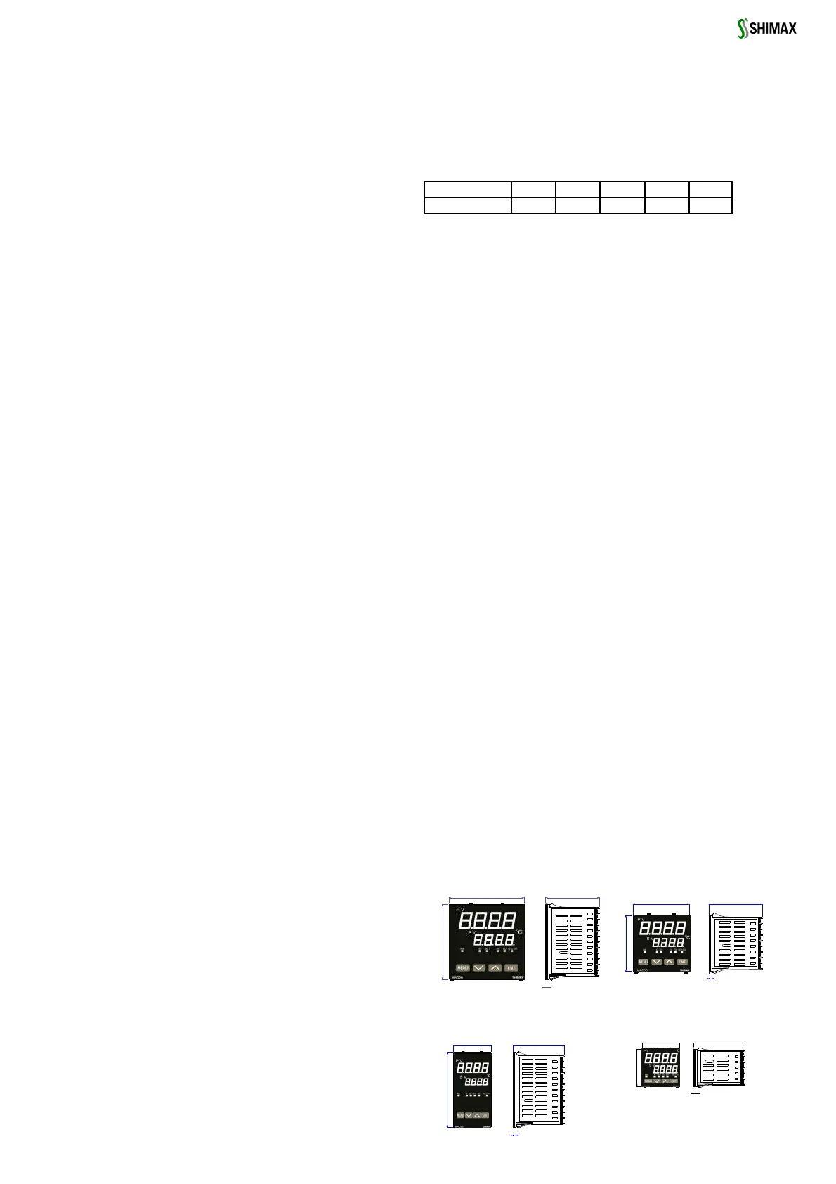
-3. External dimension and panel cutout
3. External dimension and panel cutout 3. External dimension and panel cutout
3. External dimension and panel cutout
(unit: mm)
MAC
MACMAC
MAC5
55
5A-
A-A-
A- M
MM
M C
CC
C F-
F-F-
F- E
EE
E C
CC
C
1 2 3 4 5 6
MAC5C 72mm*72mm
MAC5C 72mm*72mmMAC5C 72mm*72mm
MAC5C 72mm*72mm
MAC5D 48mm*48mm
MAC5D 48mm*48mmMAC5D 48mm*48mm
MAC5D 48mm*48mm
96
9
6
4
68.4
48
9
6
4
65.4
48
4
8
4
65.5
MAC5B 48mm*96mm
MAC5B 48mm*96mmMAC5B 48mm*96mm
MAC5B 48mm*96mm
4
68.4 72
7
2
MAC5A 96mm*96mm
MAC5A 96mm*96mmMAC5A 96mm*96mm
MAC5A 96mm*96mm
 Loading...