Section 7
Cylinde
rs
an
d
Pistons
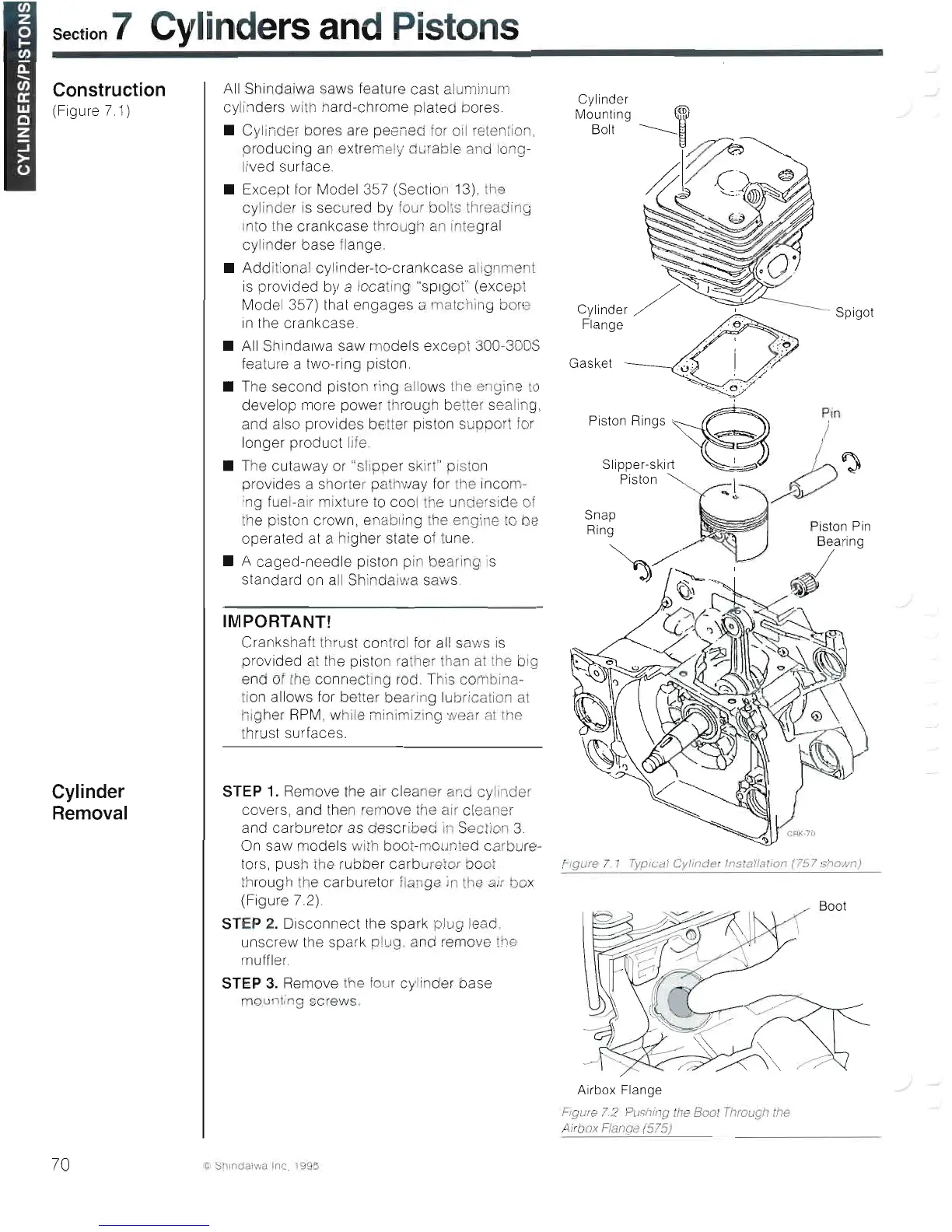
Construction
(
Fi
gure 7
.1
)
Cylinder
Removal
AII
Shindaiwa saws leature cast alu
lin
um
cyl
in
ders with hard-chrome plated bo
re
s.
• Cylrnder bo
re
s are pee ed lor oil
ret
ention.
producing
an
extremely durable and long-
lived surlace.
• Except lor Model 357 (Section 1
3)
, Ile
cylinder is secured by
fo
ur bolts threading
into
Ih
e crankcase through an integral
cylinder base
fl
ange.
• Additio
na
l cy
li
nde
r-
to-c
ra
nkcase a
li
gnme
is
provided by a locat
in
g "s
pl
got" (except
Model 357) that engages a matc
hi
ng bore
in
the crankcase.
•
AII
Sh
in
dalwa saw models except 300-300S
fe
ature a t
wo
-r
ing piston.
• The second piston ring allows the engine lo
develop more power through better sea
ll
ng,
and also provides be
tt
er piston suppor
fo
r
longer product Ilfe.
• The cuta
wa
y
or
"slipper s
ir
" plston
provides a shor er pa hway lor I
he
inco
m-
rn
g luel-alr i
xt
ure to cool he u derside o
th
e pisto n crown , enabling lhe engi e
to
be
operated at a
hi
gher state o tune.
• A caged-needle pis
ton
p
in
bearing is
standard
on
a
ll
Sh
indaiwa saws.
IMPORTANT!
Crankshall
th
ru
st
control lor
all
saws
is
provided al
th
e pist
on
ra
th
er ha al he blg
end o Ihe connecti
9
ro
d.
This combina-
ti
on
allows lor be
tt
er be
ar
in
g
lu
bricatio al
hi
gher
RPM
, wh
ll
e
in
imizing wea a lhe
Ihrust surfaces.
STEP 1. Remove t
he
ai
r cleaner and cyllnder
cove
rs
, and t
he
n
rem
ove the alr c
le
aner
and carburetor as described
in
Section
3.
On
saw models with bool-mounted carbur
e-
tors, push lhe rubber carb retor boot
th
rough he carbu
re
tor flan ge
in
lhe a r ' ox
(Figure
72)
STEP 2.
Di
sconnect the spark plug lead,
unscrew t
he
spa
rk
plug. and
re
move lhe
mulller.
STEP 3. Remo
ve
t e
fo
ur
cyl
in
der base
rn
ou
nting screws.
Cylinder /
Spigot
Flange
Gasket
p¡n
Fi
gure
7 1 Typ1cal
Cyllnder
InstaJ/a
/i
on
(757
sl1own)
Airbox Flange
Figure 1.2 Pushil
(1
he
8001 Through Ihe
Airbox Flaflge
(515)
fi
ShlnOaiwiJ Ine. 19 5
70
 Loading...