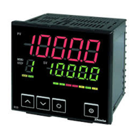
When the input type is TC K type only, designate a range when ordering.
The options [C5], [W] and [SM] cannot be applied together. (Only one option can be applied.)
When ordering:
Choose a type from the table above with alphanumeric characters.
Enter a rated scale (only for TC K type) and supply voltage using comma (,).
1.3 How to indicate the model name plate
Model name plates are put on the case and the bottom side of the internal assembly.
[Model name plate] [Example]
(1) FCL-13A-R/M Relay contact output, Multi-range input
W(20A) Heater burnout alarm output [The specified current value
BK is enterd in ( ).]
(3) No. Color, black
(1): Model name
(2): Option codes
(3): Instrument number (Indicated only on the internal assembly)
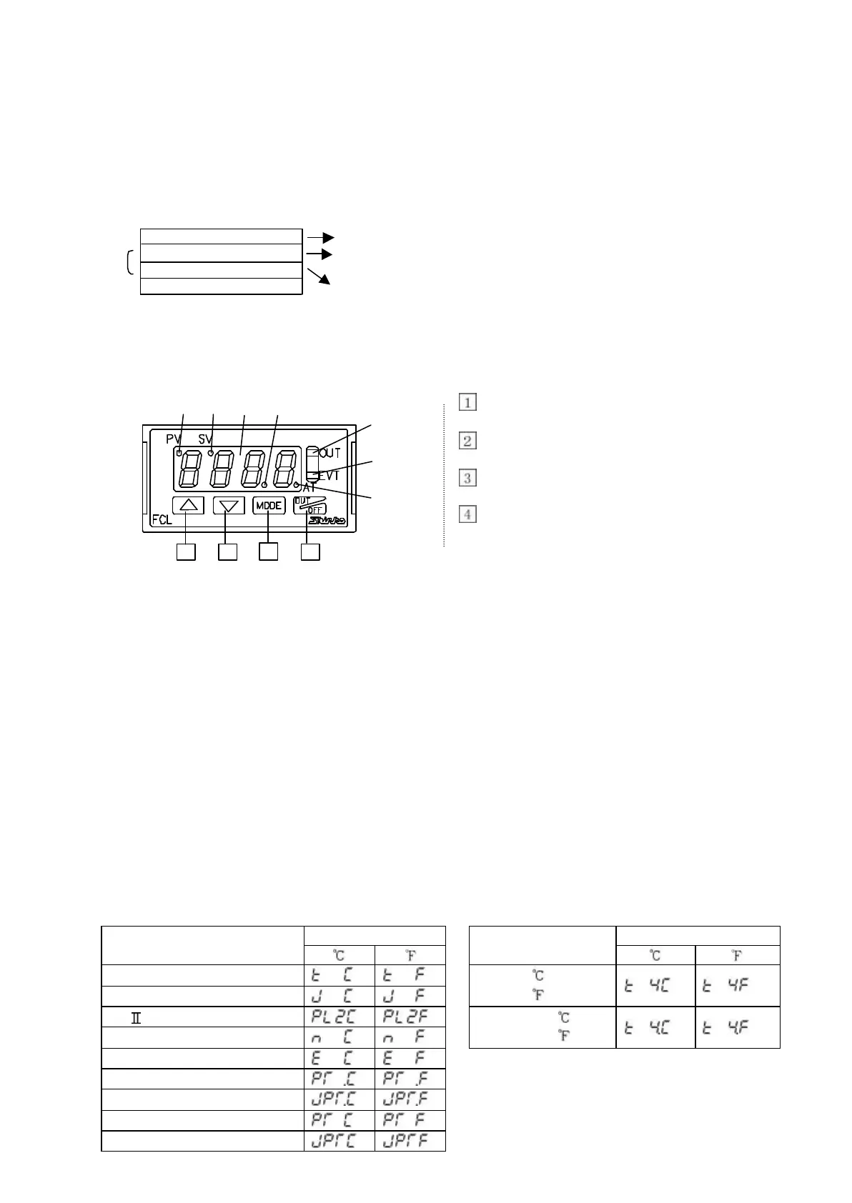
2. Name and functions of the section
(1) (2) (3) (4) Increase key : Increases the
(5) numeric value.
Decrease key : Decreases the
(6) numeric value.
MODE key : Selects the
(7) setting mode.
OUT/OFF key : Turns the control
output ON or OFF.
1 2 3 4
(1) PV indicator : The red LED lights up while Process variable is being indicated on the PV/SV display.
(2) SV indicator : The red LED lights up while Setting value is being indicated on the PV/SV display.
It blinks while being controlled with the main setting 2.
(3) PV/SV display : Indicates the process variable, setting value and characters with red LED.
(4) Decimal point : The red LED lights up when decimal point is applied to the setting value.
indicator It blinks when Manipulating value (MV) is being displayed.
(5) Control output : The green LED lights up when the control output is ON.
indicator
(6) Event output : The red LED lights up when the Temperature alarm, Loop break alarm or
indicator Heater burnout alarm is ON.
(7) Auto-tuning : The red LED blinks while the Auto-tuning or Auto-reset is being performed.
action indicator
3. Operation
PV/SV display indicates the characters of the sensor type and temperature unit for approx.
2 seconds after the power is turned on. During this time, all outputs and the LED indicators are
in their off status. (Refer to table 3.1-1 and 3.1-2.)
After that, actual temperature or the main setting value is indicated, and control starts.
(If PV display is selected in PV/SV display selection, the actual temperature will be indicated.
If SV display is selected, the main setting value will be indicated.)
[Table 3.1-1] [Table 3.1-2]
PV/SV display PV/SV display
Input
Thermocouple K
input only
K
J
0 to 400
0 to 750
PL-
N
0.0 to 400.0
0.0 to 750.0
E
Pt100 (With decimal point)
JPt100 (With decimal point)
Pt100
JPt100
(2)


 To Next Page
 Loading...