LBL 61876 rev. E, March 2018 EN 4
3.2 Control and Indicator Functions
Turns IVL Generator on or off.
Refer to 3.1 IVL Generator Front View
Press to activate the IVL Generator.
IVL Connector Cable and a valid IVL Catheter must be
connected to activate.
On green when IVL Generator is on.
Refer to 3.1 IVL Generator Front View
On yellow when user action is required regarding the IVL Catheter (CATH).
On red when internal diagnostics have detected a problem (SYS).
BATTERY CAPACITY
Display/ Charging Status
Indicates battery charge remaining.
Indicator
Lightning bolt symbol appears when the Charger Module is connected and is charging
the battery from mains power.
Charge IVL Generator before use. See Sections 5.2 and 5.3.
IVL Catheter Balloon Diameter and Length
When IVL Connector Cable and valid IVL Catheter
connected.
Number of Pulses available.
Counts down from available Pulse Count Per Catheter during
treatment as each pulse is delivered. Refer to applicable IVL
Catheter IFU for the Max Pulse Count.
On green when the device is ready to deliver therapy. Flashes to indicate therapy is
in process. On yellow when therapy is paused or deactivated.
See Section 4, Steps 5 – 9.
3.3 Front Panel Connectors
Slide right to connect charger.
Slide left to connect IVL Connector Cable.
Used to connect to charger module.
Used to connect to IVL Connector Cable (the Connector Cable connects the IVL
Generator to the IVL Catheter).
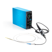
3.4 IVL Connector Cable
Pressing and holding the THERAPY CONTROL on the IVL Connector Cable initiates therapy delivery. The IVL Generator must first be activated (THERAPY STATUS indicators on
IVL Generator front panel and CATHETER CONNECTOR will be green). Refer to Section 4.0, Step 8 for more information.
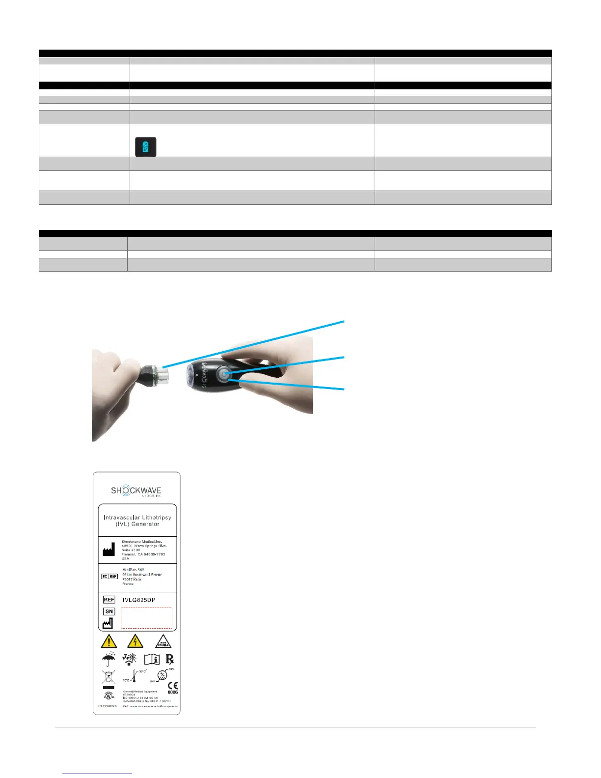
3.5 IVL Generator – Rear View
There are no controls or indicators on the rear of the IVL Generator. Refer to Appendix B for more information regarding the symbols used.
Therapy Control
Therapy Status