-4-
D4666 Heavy-Duty Mobile Base
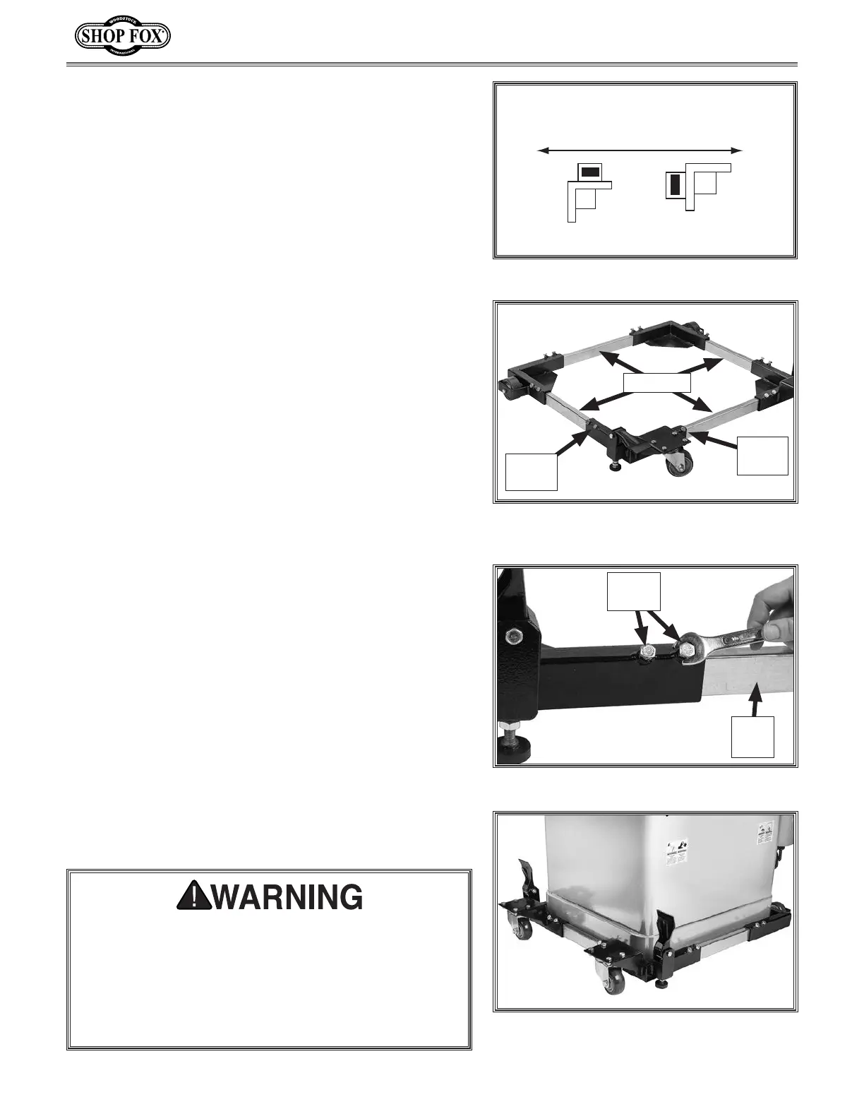
Figure 9. Measuring inside width of mobile
base.
Insert
Rail
Measure
Hex
Bolts
Figure 11. Example of machine placed
inside mobile base.
5. Orient fixed casters in same direction that machine
will typically be moved (see Figure 8). Mounting
fixed casters in wrong direction may make it difficult
to move mobile base around in small spaces.
Typical Direction of Movement
(TOP VIEW OF CASTER)
CORRECT INCORRECT
Figure 8. Fixed caster orientation.
6. Measure your machine base.
7. Slide each side rail into a corner bracket. Adjust
each side rail until mobile base inside measurement
(see Figure 9) matches base measurement of your
machine.
8. Secure each side of side rails to corner brackets
using (2) M8-1.25 x 16 hex bolts in corner
brackets (see Figure 10).
Tip: Providing an extra
1
⁄4" of space around the base
measurement allows for easier machine fit during
assembly.
9. With the help of an assistant, or proper lifting equip-
ment, lift and position machine inside mobile base
(see Figure 11).
10. Check to make sure the machine is properly seated
on the pads and that there is no sign of stress or
deflection in the mobile base.
— If there is any deflection, immediately remove the
machine from the base and check that all fasten-
ers have been tightened and the base is properly
assembled. If this does not solve the problem,
double check the weight specification of the
machine and make certain it does not exceed the
load limit listed in Specifications on Page 1.
Each side rail-to-bracket connection must use both
hex bolts, making a total of four bolts at each corner.
DO NOT load machine onto base until all bolts have
been installed and tightened. Loading a machine
onto base before completing assembly can result in
machine falling or tipping over, resulting in serious
personal injury.
Figure 10. Securing rail to corner bracket.
Hex
Bolts
Side
Rail
 Loading...