-6-
D4666 Heavy-Duty Mobile Base
6. While an assistant lifts one side of the machine,
slide rail-bracket assembly from Step 5 under
machine, as shown in Figure 16.
Note: It may be necessary to re-adjust position of
rails once machine is actually on base assembly.
Side rails may be cut down to accommodate
machines with smaller footprints. However, reduc-
ing length of mobile base decreases stability and
increases likelihood of tipping tall or top-heavy
machines. Base plates should be constructed for tall
or top-heavy machines (see Page 8).
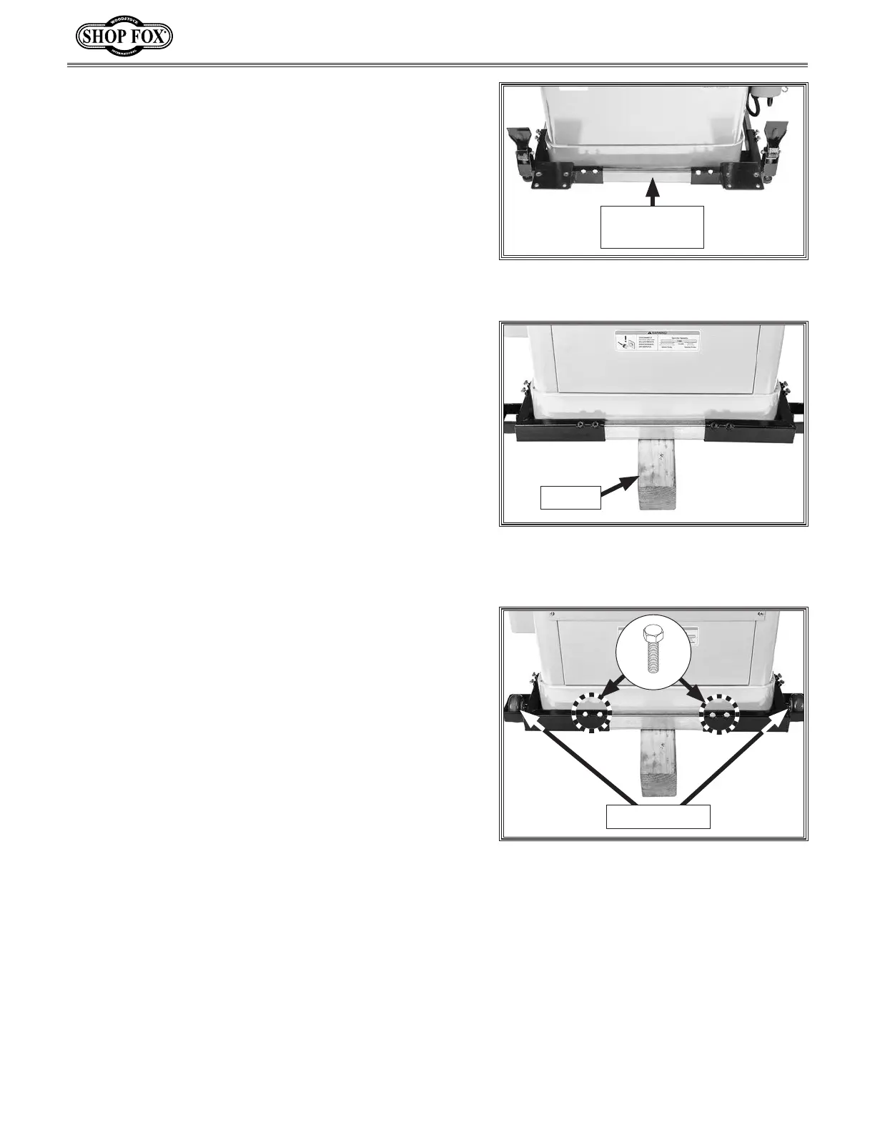
7. With the help of an assistant, lift rear side of
machine, then place a 4x4 block under machine
(see Figure 17).
8. Slide each of the corner brackets onto remain-
ing side rail, and slide assembly into rail-bracket
assembly from Step 6. Adjust fit until rail-brack-
et assembly rests against machine body (see
Figure 17).
Figure 16. Rail-bracket assembly placed
under front of machine.
Rail-Bracket
Assembly
12" 4x4
Figure 17. Remaining brackets and rail
placed around back of machine, which is
raised up with a wood block
9. Secure rail to corner brackets using (4) M8-1.25 x 16
hex bolts, as shown in Figure 18.
10. With machine still propped on 4x4 block, install both
fixed wheels using (2) M10-1.5 x 55 shoulder bolts
(see Figure 18).
11. With the help of an assistant, shift machine to
remove 4x4 block.
Figure 18. Remaining rail-bracket
assembly secured.
Fixed Wheels
x 2
 Loading...