-7-
D4666 Heavy-Duty Mobile Base
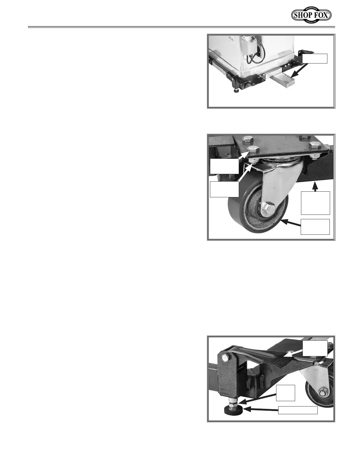
Figure 20. Swivel caster attached front
corner bracket.
Swivel
Caster
Hex Bolt
(1 of 4)
Lock Nut
(1 of 4)
12. With the help of an assistant, tilt machine, and
insert a 2x4 block beneath machine and mobile base
frame (see Figure 19).
Figure 19. 2x4 Placed beneathe machine
and mobile base frame.
12" 2x4
13. Attach each swivel caster to corner of assembly
using (4) M8-1.25 x 16 hex bolts and (4) M8-1.25 lock
nuts (see Figure 20).
Note: Patience is required when installing fasteners
inside the bottom of the caster wheels due to space
constraints.
14. With the help of an assistant, tilt machine and
remove 2x4 block from beneath machine and mobile
base frame, and set machine on the floor.
Note: When moving the mobile base, the rubber
feet should not touch the floor. However, when
operating the machine, ensure that the rubber feet
are fixed firmly against the floor to stabilize the
machine.
Adjusting Rubber Feet
The height of the rubber feet can be adjusted to stabi-
lize the machine. To ensure the machine does not move
during operations, always make sure the swiveling caster
wheels (see Figure 21) are not touching the ground before
operating the machine.
Tool Needed Qty
Open-End Wrench 17mm.......................................1
To adjust rubber foot height, do these steps:
1. Lower swiveling caster to the ground by lifting foot
pedal up (see Figure 21).
IMPORTANT: When moving mobile base, rubber feet
should not touch the floor. Likewise, when operating
the machine, ensure that the rubber feet are fixed
firmly against the floor to provide stability.
2. Loosen hex nut on each rubber foot to allow foot
(see Figure 21) to move up or down as needed, then
re-tighten each hex nut.
3. Press down on foot pedal to raise swiveling casters
off ground at least
1
⁄8".
— If casters do not clear floor by at least
1
⁄8", repeat
Steps 1–2 until they do so.
Figure 21. Rubber foot adjustment.
Rubber Foot
Hex
Nut
Foot
Pedal
Front
Corner
Bracket
 Loading...