Assembly and
Setup
Guard Assembly
Assemble and set up the guard as-
sembly accordin§
to
the following
procedures:
1.
Attach
the brackets
to
the guard.
Attach the
two
brackets
(29)
to
the
guard
(21)
with the carriage
bolts
(31),
washers
(30),
washers
(28)
and wing
nuts
(27)
. With the hardware at the
back
of
the
guard's
two
outer
slots,
tighten the wing nuts finger tight.
2.
Install the guard assembly
on
the
channel.
In
the
slot
of
each bracket
(29),
loosely assemble a screw
(23),
washer
(24),
two
special washers
(25)
and
aT-nut
(26).
Insert the edge
of
the T-nut into the channel first, then
pivot the T-nut and push it down into
the channel. Raise the guard all the
way up the bracket and use a 5/16" Al-
Ien wrench
to
tighten the screw
(23).
Channel and Support
Bracket Assembly
Assemble and set up the channel and
support bracket assembly according
to
the following procedures:
1.
Install the
two
support brackets
and clamps. (See Figure
9.)
Place the
channel
(13)
with
the guard and tem-
plate support assemblies attached
across a corner
of
your workbench. Use
the 5/16" Allen wrench to attach the
support brackets
(15)
to
the channel
with screws
(19)
and washers
(20)
at
the third hole from each end
of
the
channel. Secure a clamp
(16)
to
each
support bracket
(15)
with
a screw
(18)
and washer (17).
NOTE
The placement of the left-hand
support bracket on the channel is
for
maximum
spindle
capacity.
Depending on the operation being
performed, it should
be
moved
to
the right as required to provide
more rigid support.
\
\
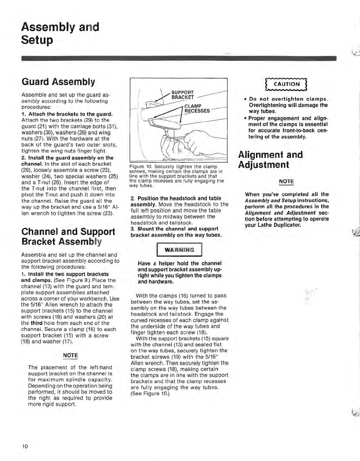
Figure
10. Securely
tighten
the
clamp
.
screws, making certain the
clamps
are
In
line
with
the
support
brackets and
that
the
clamp
recesses are fully engaging
the
way tubes.
2.
Position the headstock and table
assembly.
Move the headstock
to
the
full
left
position and move the table
assembly
to
midway between the
headstock and tailstock.
3.
Mount
the channel and support
bracket assembly on the way tubes.
WA
RNING
Have a helper hold the channel
and support bracket assembly up·
right while you tighten the clamps
and hardware.
With the clamps
(16)
turned to pass
between the way tubes, set the
as-
sembly on the way tubes between the
headstock and tailstock. Engage the
curved recesses
of
each clamp against
the underside
of
the way tubes and
finger tighten each screw
(18).
With the support brackets
(15)
square
with
the channel
(13)
and seated flat
on the way tubes, securely tighten the
bracket screws
(19)
with the 5/16"
Allen wrench. Then securely tighten the
clamp screws (18), making certain
the clamps are in line with the support
brackets and
that
the clamp recesses
are
fully
engaging the way tubes.
(See Figure
10.)
• Do
not
overtighten
clamps.
Overtightening
will
damage the
way tubes.
• Proper engagement and align·
ment
of
the clamps is essential
for
accurate front·to·back cen·
tering
of
the assembly.
Alignment and
Adjustment
NOTE
When you've completed all the
Assembly
and
Setup instructions,
perform all the procedures in the
Alignment
and
Adjustment
sec·
tion
before
attempting
to
operate
your Lathe Duplicator.
,
10
 Loading...