Alignment
and
Adjustment
Alignment and
Adjustment
After you've completed the Assembly
and Setup instructions, perform all
the instructions
in
this Alignment and
Adjustment section before operating the
Lathe Duplicator.
Also, whenever you remount the
Lathe Duplicator on the Mark V
be
sure
to check the "Table to Lathe Centers
Parallelism," "Template Centers Align-
ment," and "Follower to Cutter
Alignment."
The precise alignment of the Lathe
Duplicator is critical
for
exact
duo
plication.
If
the alignment is not
done properly, you'll waste time
and materials, and find duplicat·
ing extremely frustrating.
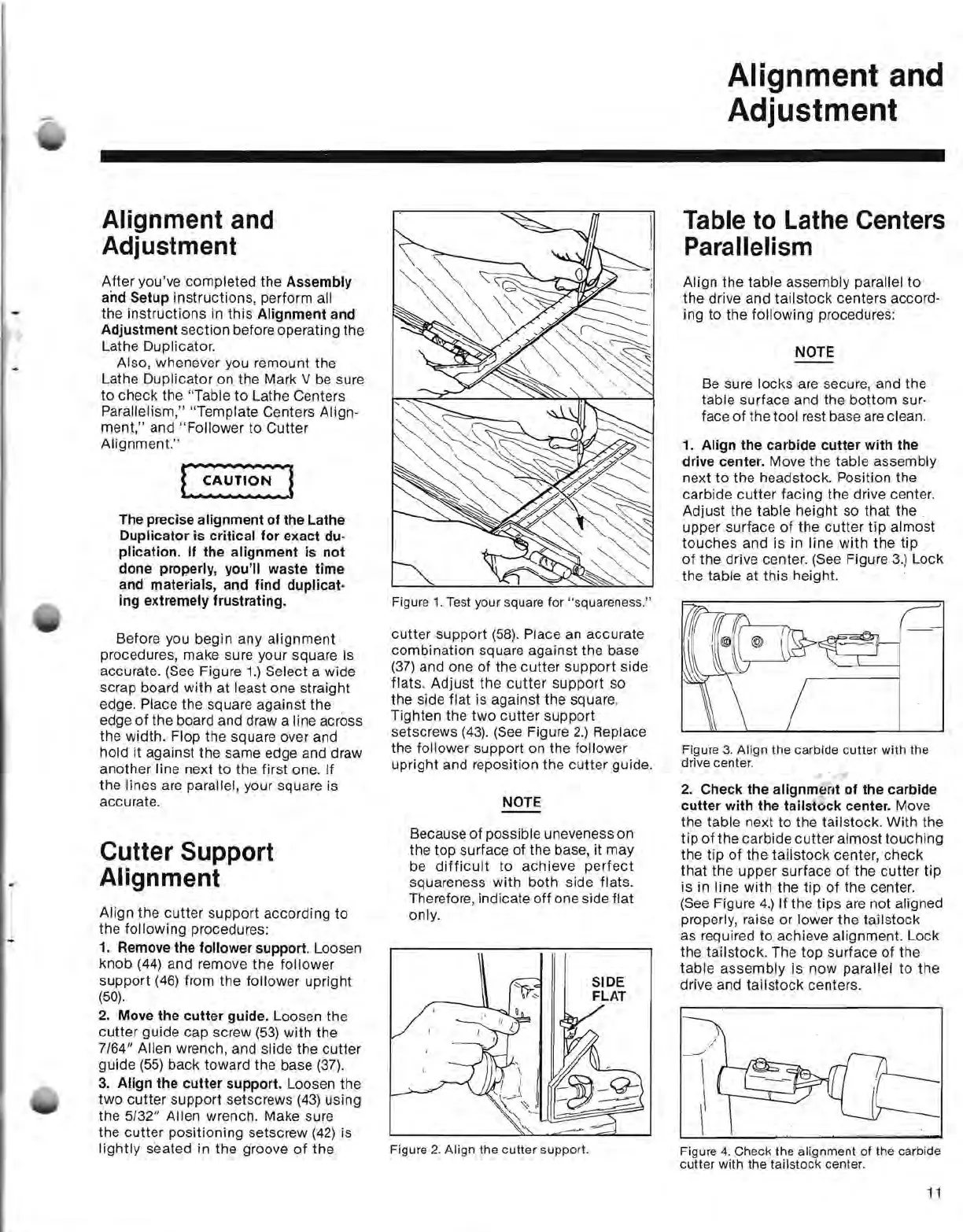
Before you begin any
alignment
procedures, make sure your square is
accurate.
(See
Figure
1.)
Select a wide
scrap board with at least one straight
edge. Place the square against the
edge
of
the board and draw a line across
the width. Flop the square over and
hold it against the same edge and draw
another line next to the first one. If
the lines are parallel, your square is
accurate.
Cutter Support
Alignment
-
Align the cutter support according
to
,
the following procedures:
1.
Remove the follower support. Loosen
knob
(44)
and remove the follower
support
(46)
from the follower upright
(50).
2.
Move the
cutter
guide. Loosen the
cutter guide cap screw
(53)
with the
7/64" Allen wrench, and slide the cutter
guide
(55)
back toward the base
(37).
3.
Align the
cutter
support. Loosen the
two
cutter support setscrews
(43)
using
the
5/32" Allen wrench. Make sure
the cutter positioning setscrew
(42)
is
lightly
seated in the groove
of
the
Figure 1. Test your square for "squareness."
cutter support
(58).
Place
an
accurate
combination square against the base
(37)
and one of the cutter support side
flats. Adjust the
cutter
support so
the side flat is against the square.
Tighten the
two
cutter support
setscrews
(43).
(See
Figure
2.)
Replace
the follower support on the follower
upright and reposition the
cutter
guide.
NOTE
Because of possible uneveness on
the top surface of the base, it may
be
difficult
to
achieve
perfect
squareness with both side flats.
Therefore, indicate
off
one side flat
only.
Figure
2.
Align
the
cutter
support.
Table to Lathe Centers
Parallelism
Align the table assembly parallel to
the drive and tailstock centers accord·
ing to the following procedures:
NOTE
Be
sure locks are secure, and the
table surface and the bottom sur·
face
of
the tool rest base
are
clean.
1.
Align the carbide
cutter
with
the
drive center. Move the table assembly
next
to
the headstock. Position the
carbide cutter facing the drive center.
Adjust the table height so that the
upper surface
of
the cutter tip almost
touches and is in line with the tip
of
the drive center.
(See
Figure
3.)
Lock
the table at this height.
Figure
3.
Align the carbide
cutter
with the
drive center.
2.
Check the alignment
of
the carbide
cutter
with the tailstock center. Move
the table next to the tailstock. With the
tip
of
the carbide
cutter
almost touching
the tip
of
the tailstock center, check
that the upper surface of the cutter tip
is in line with the tip
of
the center.
(See
Figure 4.) If the tips
are
not aligned
properly, raise or lower the tailstock
as required to achieve alignment. Lock
the tailstock. The top surface of the
table assembly is now
parallel
to
the
drive and tailstock centers.
Figure 4. Check the alignment
of
the carbide
cutter
with
the
tailstock
center.
11
 Loading...