Page 27
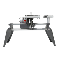
845180 SHOPSMITH MARK V
Extension Table is even with the infeed
and outfeed surface Worktable.
7. Check that the Extension Table Fence
Mounting Rail is in line with the Fence
Mounting Rail on the Worktable.
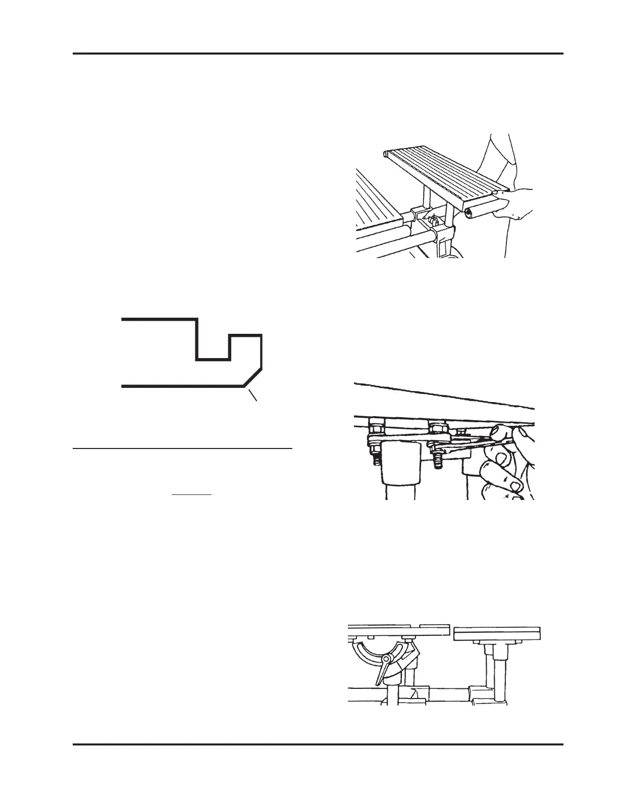
8. Lay a Straightedge across the bevel of
both Rails. (Figure 86). If adjustment is
needed, loosen (1/2 turn) the four Bolts
holding the Extension Table to the Ex-
tension Table Base. Tap the Extension
Table forward or backward until the
bevel of the Fence Mounting Rails are
aligned. Retighten the Bolts by turning
each a small amount until all four are
secure. Check the alignment.
Figure 86
ALIGN THE EXTENSION TABLE
(MARK V MODELS 500 SYLE 2, 510 & 520)
NOTE
These instructions are for aligning the Extension
Table on the right side of the Headstock. You can
also follow these same procedures to align it to the
left side of the Headstock.
For most projects, align the Extension Table on the
right side. It is also occasionally used on the left
side. However, once the Extension Table is aligned
on the right side, it cannot be transferred to the left
side and still maintain precise alignment.
If you wish precise alignment on the left side,
repeat the following instructions - but place the
Extension Table on the left side in the Headstock.
1. Mount the Extension Table in the MARK
V's Accessory Base Arm (on the right
side) at a comfortable height, as shown
in Figure 87.
Figure 87
2. Use a 1/2" Wrench to loosen the Bottom
Nuts holding the Table Base to the Table
approximately 1/2" from the bottom of
the Table. This will allow you room for
later adjustment. See in Figure 88.
Figure 88
3. The Worktable should already be
mounted in the Carriage Mount. Move
the Worktable next to the Extension Table
and adjust it to about 1/4" above the
Extension Table, as seen in Figure 89.
Figure 89
Fence
Rail
Bevel