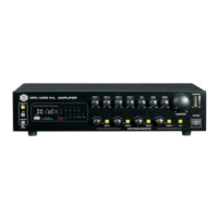
4. CONTROL ELEMENTS
Power Switch
It powers the PSA Professional Stereo Amplifier ON and OFF.
Power LED
This power LED lights up when the unit is powered up.
Clip LEDs
These LEDs will light up when distortion reaches a level of 0.5%, turn the relative
gain control down so that the clip LEDs only flash occasionally. And these LEDs
will light up when the unit is in protection mode due to overheating, exist DC output
or other causes.
Signal LEDs
These LEDs will light up when the signal at the output is at least 100 mV.
Gain Controls
These controls are used to adjust the output signal level. In stereo mode, they
are used to control the level of respective channel; In bridge mode, only the gain
control of channel A is used to control the volume of the whole system.
1
2
3
4
6
Front Panel
-2-
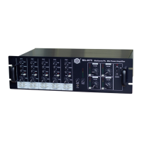
Rear Panel
7
61012
914
118
13
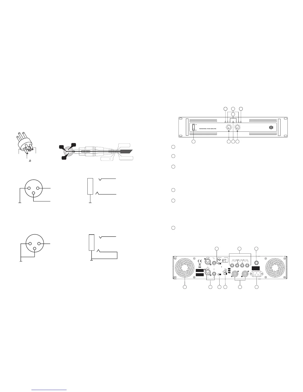
Connect input signal to mix balanced MIC input socket: balanced input (6-1),
unbalanced input (6-2). It is suggested to use the balanced input especially
when the audio cable is very long, this will effectively reduce "hum" noise
caused by AC power.
6. CONNECTION FOR INPUT SIGNAL
Pin1( )
Pin2 (+)Pin3 (-)
GROUND
HOT (+)
COLD ( )
3
2
1
-5-
GND
(-) Input
(+) Input
(+) Input
(-) Input
GND
Fig. (6-1) Balanced input
(+) Input
GND
GND
(+) Input
Fig. (6-2) Unbalanced input
12
3
BRIDGED INPUT
CH-B
LINE
BALANCED
INPUT
LINE
CH-A
CLIP LIMT
OFF ON
BRIDGED
STEREO
PARALLEL
(MONO)
OFF ON
LF 30HZ
FILTER
1.15V/20K
INPUT
CONNECTION
(+)
-
()
(GND)
SRT
T(+)
S(GND)
R( )
-
CH-A CH-B
BRIDGED
MONO
CHANNEL A CHANNELB
BREAKER
SERIAL
MODEL
CHA
1+
1+
1+
1
+
2
BRIDGEDBRIDGED
CHB
1
2
1
3
PUSH
2
1
3
PUSH
In normal operation, the Led will not illume; If the Led is red, it means the unit is in
heat protection, no sound is output. The speaker system is actually disconnected
from the amplifier outputs when this LED is red, the temperature must be lowered
by better ventilation and decrease the signal level etc. if the problem is corrected,
the protection systems deactivate automatically, and normal amplifier operation is
resumed.
1 2
4
3
5
6 6
5
4
Protection LEDs