Low Frequency Filter
This filter rolls off audio signals below 30 Hz. In this way bass performance will be
improved, because the subsonic motion of the cone will be cut out and more power
is made available to the woofer in the audible range of frequencies. If you want our
view: keep the filter on most of the time unless you are filtering the signal before the
input of the amplifier. Especially vented speakers (bass-reflex) are very sensitive to
subsonic frequencies (below 30 Hz).
12
Circuit Breaker
This is an electronic fuse for protecting the unit from possible damage. When the unit
is overloaded or the temperature inside the unit is too high, this push-type button will
spring out and disconnect the power supply. Push the breaker to restore normal
working conditions.
IEC Socket for AC Power Cable
Connect the supplied main cord. Do not insert the power cord into the amplifier and
into the AC outlet until voltage has been correctly set.
XLR Balanced Input Connectors
Each channel features balanced XLR and 1/4" jack sockets wired in parallel. The
balanced signals are less sensitive to hum noise generated by AC.
Speakon Outputs (channel A & channel B)
These connectors are specifically designed to connect high power speakers. The
correct polarity is secured automatically, they prevent shock hazard and they lock-in
securely.
Binding Post Outputs (channel A & channel B)
Please make sure to respect the speaker polarity when using binding post.
urn off the unit before connecting an audio signal to the binding post toCaution: T
avoid any electric shock!
6
7
8
9
10
Clip-limiter switch
If a very high level signal is driven into the amplifier, the output signal will clip, that
the peaks of the waveform will be flattered. The clip limiter circuit automatically
reduces the gain to prevent the overdrive. You can switch the clip limiter circuit on
and off via the switch on the rear panel of your amplifier. If you use full range speakers,
the clip limiter circuit will reduce the high frequency distortion and it will also protect
the high frequency drivers. However, some users prefer to switch the limiter off to
get more punch from kick drums and other sounds in the low frequencies area.
11
-3-
-4-
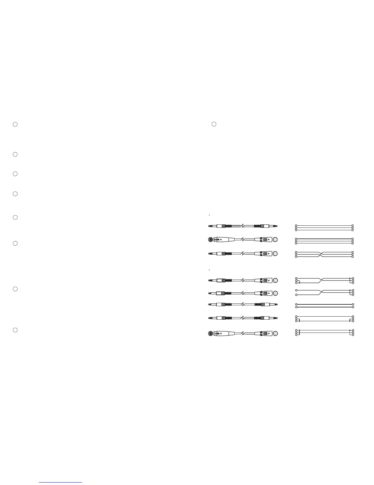
5. WIRING CONFIGURATION
- Parallel Mono Mode
In this mode, channel A input signal will be output from the output connectors
of both channels.
- Bridged Mode
In this mode, channel A input signal will be output from the bridge-mono output
connector.
Output Mode Selector
The PSA series professional stereo amplifiers present three operating modes:
- Stereo Mode
In this mode, channel A and channel B operate independently (as a normal stereo
amplifier). The channel A input signal will be output from the channel A output
connector, and channel B input signal will be output from the channel B output
connector.
14
Cooling Fan
This fan secures enough cooling for your amplifier. The airflow is front-to-rear.
The fan speed is electronically regulated depending on the temperature of the
power devices.
13
1
2
3
1
2
3
12
3
2
1
3
Tip
Sleeve
1
2
3
TIP SLEEVE
12
3
Tip
Ring
Sleeve
1
2
3
TIP RING SLEEVE
12
3
Tip
Sleeve
Tip
Sleeve
TIP SLEEVE
SLEEVE TIP
Tip
Ring
Sleeve
Tip
Ring
Sleeve
TIP RING SLEEVE
SLEEVE RING TIP
Tip
Ring
Sleeve
1
2
3
TIP RING SLEEVE
12
3
1
2
3
1
2
3
21
3
12
3
Tip
Ring
Sleeve
Tip
Ring
Sleeve
TIP RING SLEEVE
SLEEVE RING TIP
Unbalanced Input
Balanced Input
 Loading...