D
dianakennedyAug 8, 2025
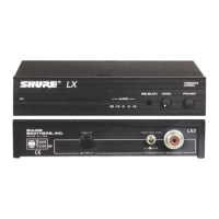
Why is my Shure Microphone system signal noisy?
- PPenny DavisAug 8, 2025
A noisy signal from your Shure Microphone system could be due to several factors. First, check the Power/Battery Fuel Gauge and replace the battery if the power is low. Also, try to remove any local sources of RF interference, such as lighting equipment. If you are using a guitar or other instrument, ensure it is connected to the LX1 with a Shure WA302 adapter cable. Two transmitters might be operating on the same frequency, so locate and turn one off. The signal may also be too weak, so reposition the antennas and, if possible, move them closer to the transmitter. Lastly, adjust the receiver squelch control.