BATTERY
OPERATION
Battery Supply
The M67 is designed so that
it
may be operated with
an external battery or well filtered
DC
supply pro-
viding 30 Volts DC. Current drain is under 6 ma. at
+
I0 dbm output level.
The
DC
input terminals are located adiacent to the
power cord on the rear panel and are designated "30
Volts
DC"
"
-I-"
and
"-".
The use of battery supplies designed for the M67 (see
Accessory List)
is
recommended both for convenience
in connecting and mounting and to permit use of the
automatic power change-over feature.
Automatic Power Change-Over
When used with Shure accessory power supplies, the
M67 may be operated from the
AC
power line with the
battery supply connected. In this configuration, the unit
will automatically switch to battery operation should
AC
voltage fall below a suitable level. This change-over
is completely automatic, instantaneous, and completely
noiseless. Should line power fail completely, the
VU
meter lamps will extinguish, providing a visual indica-
tion of the line failure.
If
use of a 30-volt
DC
supply
other than Shure Battery Supplies
is
desired, the
automatic change-over feature may be retained by
connecting a suitable silicon diode (Shure
RKCPI)
in series with the positive lead. The cathode (band)
end connects to the
+30-Volt
DC
terminal.
Battery Check
Battery condition may be determined
by
use of the
"Battery Check" position of the main power switch
adjacent to the
VU
meter. This check must be made
with the
AC
line cord disconnected. The check pro-
cedure is as follows:
With
the
AC
line cord disconnected, leave power
switch in
"ON"
position for at least ten seconds
(to discharge filter capacitors), then move switch
up to "Battery Check." Observe reading on
VU
meter.
A
new battery will give about a +2VU Indi-
cation. Battery condition is good
if
meter indica-
tion is above
0
VU
(red end of scale). 0 VU or below
indicates that battery must be replaced for proper
operation.
For best performance on battery operation at
temperatures below
40"
F.,
change batteries when
Battery Check meter reading is I
.O
VU or lower.
NOTE:
This check interrupts power to the ampli-
fiers, and therefore, should be made only
when the unit is not in operation.
DC Power Take-Off
With
AC
operation, the "30-Volt
DC"
terminals are
energized with polarity shown and may be used to
power up to two additional
M67's or other 30-volt
DC
low drain accessories.
ACCESSORIES
A67B Battery Supply
This unit is designed to power the
M67
at
full
rated
output. Battery life is approximately 70 hrs at
+
10
dbm and 85 hrs at
+4
dbm output at
4
hours use
per day. See temperature note below.
It
may be used either as the sole power source or as
a stand-by
safety during
AC
operation, providing
automatic, noiseless switchover in case of
AC
failure.
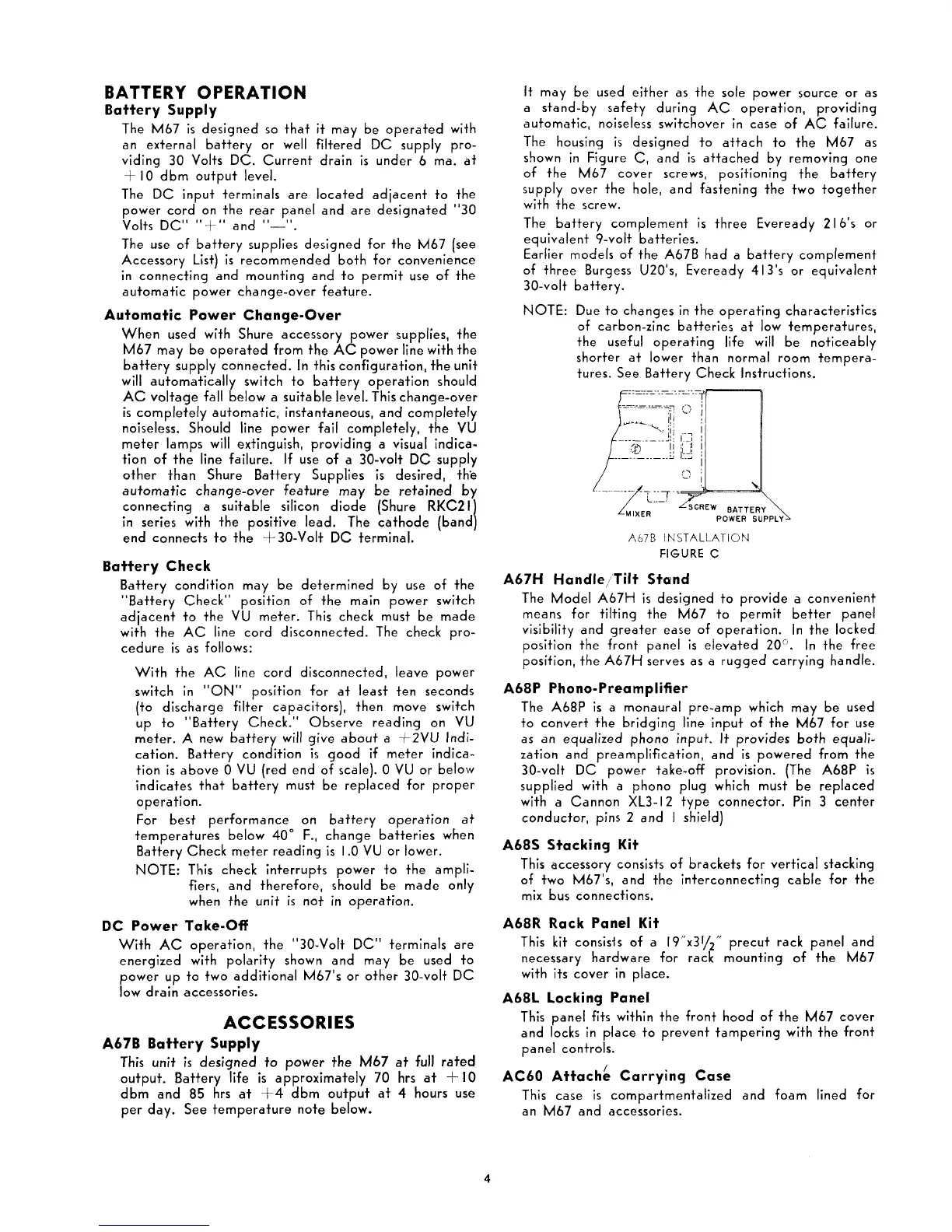
The housing
is
designed to attach to the M67 as
shown in Figure
C,
and
is
attached by removing one
of the M67 cover screws, positioning the battery
supply over the hole, and fastening the two together
with the screw.
The battery complement
is
three Eveready
2
16's or
equivalent 9-volt batteries.
Earlier models of the
A67B had a battery complement
of three Burgess
U201s, Eveready 413's or equivalent
30-volt battery.
NOTE: Due to changes in the operating characteristics
of carbon-zinc batteries at low temperatures,
the useful operating life will be noticeably
shorter at lower than normal room tempera-
tures. See Battery Check Instructions.
A67B
INSTALLATION
FIGURE
C
A67H HandleiTilt Stand
The Model A67H
is
designed to provide a convenient
means for tilting the M67 to permit better panel
visibility and greater ease of operation. In the locked
position the front
panel
is
elevated 20". In the free
position, the
A67H serves as a rugged carrying handle.
A68P Phono-Preamplifier
The A68P is a monaural pre-amp which may be used
to convert the bridging line input of the M67 for use
as an equalized phono input.
It
provides both equali-
zation and preamplification, and is powered from the
30-volt DC power take-off provision. (The
A68P is
supplied with a phono plug which must be replaced
with a Cannon
XL3-I2 type connector. Pin
3
center
conductor, pins
2
and
I
shield)
A68S Sfacking Kit
This accessory consists of brackets for vertical stacking
of two
M67's, and the interconnecting cable for the
mix bus connections.
A68R Rack Panel Kit
This
kit
consisis of a 19"x31/2" precut rack panel and
necessary hardware for rack mounting of the M67
with its cover in
place.
A68L Locking Panel
This panel fits within the front hood of the M67 cover
and locks in place to prevent tampering with the front
panel controls.
AC60 ~ttach: Carrying Case
This
case is compartmentalized and foam lined for
an M67 and accessories.

 Loading...