EasyManua.ls Logo

Shure SCM410 - User Manual

Shure SCM410
25 pages
Print Icon
To Next Page IconTo Next Page
Loading...
1/25
SCM410 SCM410E -- Four-Channel Micro-
phone Mixer
Safety Information
IMPORTANT SAFETY INSTRUCTIONS
1. READ these instructions.
2. KEEP these instructions.
3. HEED all warnings.
4. FOLLOW all instructions.
5. DO NOT use this apparatus near water.
6. CLEAN ONLY with dry cloth.
7. DO NOT block any ventilation openings. Allow sufficient distances for adequate ventilation and install in accor-
dance with the manufacturer’s instructions.
8. DO NOT install near any heat sources such as open flames, radiators, heat registers, stoves, or other appara-
tus (including amplifiers) that produce heat. Do not place any open flame sources on the product.
9. DO NOT defeat the safety purpose of the polarized or grounding type plug. A polarized plug has two blades
with one wider than the other. A grounding type plug has two blades and a third grounding prong. The wider
blade or the third prong are provided for your safety. If the provided plug does not fit into your outlet, consult an
electrician for replacement of the obsolete outlet.
10. PROTECT the power cord from being walked on or pinched, particularly at plugs, convenience receptacles,
and the point where they exit from the apparatus.
11. ONLY USE attachments/accessories specified by the manufacturer.
12. USE only with a cart, stand, tripod, bracket, or table specified by the manufacturer, or sold with the apparatus.
When a cart is used, use caution when moving the cart/apparatus combination to avoid injury from tip-over.
13. UNPLUG this apparatus during lightning storms or when unused for long periods of time.
14. REFER all servicing to qualified service personnel. Servicing is required when the apparatus has been dam-
aged in any way, such as power supply cord or plug is damaged, liquid has been spilled or objects have fallen
into the apparatus, the apparatus has been exposed to rain or moisture, does not operate normally, or has
been dropped.
15. DO NOT expose the apparatus to dripping and splashing. DO NOT put objects filled with liquids, such as vas-
es, on the apparatus.
16. The MAINS plug or an appliance coupler shall remain readily operable.

Other manuals for Shure SCM410

Question and Answer IconNeed help?

Do you have a question about the Shure SCM410 and is the answer not in the manual?

Summary

Safety Information

Installation

Single Mixer (Half Rack) Installation

Instructions for mounting a single unit in a rack.

Dual Mixer (Full Rack) Installation

Instructions for mounting two units together in a rack.

SCM410 Connections

Basic Mixer Operation

Limiter

Explanation of the output limiter function and its settings.

Advanced Functions

Logic Connection Specifications

Overview of logic functions and their connection requirements.

Logic Connector

Pin assignments and functions for the DB-15 logic connector.

Suggested Logic Applications

Inhibiting Gating for Unwanted Sounds

Preventing unwanted sounds from triggering microphones using logic.

Overview

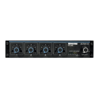
The Shure Model SCM410/E is a four-channel automatic microphone mixer designed for sound reinforcement, audio recording, and broadcast applications. It significantly enhances audio quality in scenarios requiring multiple microphones. The mixer is compatible with any low-impedance dynamic or condenser microphone, including wireless types. Multiple SCM410 mixers can be linked with other SCM410 mixers, as well as Shure Models FP410, SCM810, and SCM800, to expand the number of available inputs.

Each input channel on the SCM410/E features a two-band equalizer and three logic terminals. The equalizer helps reduce unwanted low-frequency audio pickup and allows different microphone types (lavaliers, boundary, and handheld) to sound similar. The logic terminals offer control over external devices. The SCM410 operates on 100-120 Vac power, while the SCM410E operates on 220-240 Vac power. Each mixer comes with a power cord, rack-mounting hardware, and a link cable.

Key Features:

  • Fast, noise-free microphone selection with automatic adjustment to changes in background noise.
  • Automatic gain adjustment as additional microphones are activated (NOMA - Number of Open Microphones Attenuated).
  • Last Mic Lock-On circuit to maintain ambient sound.
  • Half-rack space design for efficient installation.
  • Adjustable EQ for each channel.
  • Active balanced microphone-level XLR inputs and an active balanced Mic/Line level XLR output.
  • Unbalanced auxiliary-level phono output.
  • Bi-color channel activation and clipping LEDs.
  • Peak-responding output limiter with LED indicator.
  • Peak-responding output level meter.

Operating Principles (IntelliMix® Circuitry):

The SCM410 utilizes Shure's proprietary IntelliMix® circuitry for seamless automatic mixing, combining three functions:

  • Noise Adaptive Threshold: Distinguishes between constant background noise (e.g., air conditioning) and changing sound (e.g., speech) for each input channel. It continuously adjusts the activation threshold to ensure only speech louder than background noise activates a channel.
  • MaxBus: Controls the number of channels activated for a single sound source. One talker activates only one channel, even if multiple microphones pick up that talker.
  • Last Mic Lock-On: Keeps the most recently activated microphone open until another is activated. This prevents the audio signal from seeming lost during pauses in conversation and ensures background ambience is always present.

Front Panel Controls:

  • Microphone Channel Gain Controls 1-4: Adjusts microphone gain for each channel.
  • Input LED 1-4: Lights green when a channel is active; lights red at 6 dB below clipping level.
  • Low-Cut Filter 1-4: Provides adjustable low-frequency rolloff (high-pass) to reduce undesirable low-frequency signals.
  • High-Frequency Shelving Filter 1-4: Offers level boost or cut in the mid/high-frequency region to reduce sibilance from vocal microphones or compensate for off-axis coloration in lavalier microphones.
  • Output Level Meter: Six-segment LED meter indicating peak output signal level in dBu (0 dBu = 0.775V). The red LED illuminates at 6 dB below clipping. The last LED indicates limiter action.
  • MASTER Level Control: Controls overall output level.
  • POWER LED: Lights green when the mixer is plugged in.
  • POWER Switch: Turns the mixer on and off (country dependent).

Rear Panel Connections:

  • Power Connector: Energizes the unit (100-120 Vac for SCM410, 220-240 Vac for SCM410E). Note: No power On/Off switch on this mixer.
  • DIP Switch: A 4-position switch providing additional functions (Last Mic Lock-On, XLR Output Level, Limiter, 12V Phantom Power).
  • Microphone Logic Connector (DB-15 male): Connects to GATE OUT, MUTE IN, and OVERRIDE IN logic terminals for each channel. (Not a VGA monitor port).
  • AUX OUT Phono Connector: Feeds consumer-level audio equipment (e.g., tape recorder, VCR, video camera). Not affected by MIC/LINE switch.
  • MIC/LINE XLR OUTPUT Connector: Can be set for microphone or line-level output via a DIP switch.
  • LINK IN/OUT Connector: Permits linking multiple SCM410/E, FP410, SCM810, SCM800, or AMS8100 mixers to create additional inputs.
  • MIC LEVEL XLR INPUT Connectors: Active balanced microphone-level XLR inputs.

DIP Switch Functions:

  • Last Mic Lock-On (Switch 1): ON (factory setting) keeps the last activated mic on; UP (All mics off after hold time) turns mics off after their default hold time.
  • XLR Output Level (Switch 2): DOWN (Line Level) for line-level output; UP (Mic Level) for microphone-level output.
  • Limiter (Switch 3): DOWN (OFF*) defeats the limiter; UP (ON) activates the output limiter (default threshold +16 dBu).
  • 12V Phantom Power (Switch 4): DOWN (OFF*) disables phantom power; UP (ON) provides 12Vdc phantom power to XLR inputs for condenser microphones.

Installation:

The SCM410 can be rack-mounted (single or dual units), table-top mounted, or fixed-mounted (top or hanging). Hardware for rack mounting and rubber feet for table-top mounting are supplied. For hanging mounts, appropriate hardware rated for 15 lbs or more is recommended for surfaces other than wood.

Connections:

  1. Connect microphone signal sources to Channel Input connectors using 2-conductor shielded audio cables.
  2. Set the +12V phantom power DIP switch to ON if condenser microphones are used.
  3. Connect the SCM410 Mic/Line Level Output to the input of mixers, EQs, amplifiers, or recorders.
  4. Connect the power cord to the appropriate AC power source (100-120 Vac for SCM410, 220-240 Vac for SCM410E).

Linking Multiple Mixers:

Multiple SCM410, FP410, or SCM810 mixers can be linked via the LINK OUT and LINK IN jacks. When linked, mixers operate as a system, sharing automatic mixing functions. All input signals appear at all linked mixer outputs. Each mixer's Master level control affects only its own output. For linked mixers using logic terminals, connect the LOGIC GROUND terminals of each unit together. Use high-quality, shielded link cables and connect linked mixers to the same AC power mains to minimize hum and noise.

Basic Mixer Operation:

  1. Adjust each channel level so the Overload LED flickers only during very loud speech or noise.
  2. Adjust Low-Cut and High-Frequency controls to make microphones sound similar.
  3. Adjust the Master level control for the desired output level, indicated by the output peak meter.

Equalizer Functions:

  • Low-Cut Filter (High-Pass): Reduces unwanted low-frequency sounds (footsteps, traffic, proximity effect). One-pole, 6 dB per octave filter with adjustable cutoff from 25 to 320 Hz.
  • High-Frequency Shelving: Provides a 6 dB boost or cut at 5 kHz and above (rising to ±8 dB at 10 kHz). Useful for boosting flat frequency response, tempering sibilant vocal microphones, or enhancing off-axis lavalier microphones.

Logic Connection Specifications:

The SCM410 logic functions expand installation and control options, from simple cough switches to computer-controlled room systems.

  • GATE OUT: Goes to logic "low" (sinks current) when a microphone is gated on (500 mA sinking ability).
  • MUTE IN: Applying logic "low" (from GATE OUT or a switch closure to logic ground) gates the channel off, dropping output to -∞.
  • OVERRIDE IN: Applying logic "low" forces the channel on. Mute takes precedence if both Mute and Override are activated.
  • LOGIC GROUND: Distinct from audio ground. All logic ground connections should be made to this pin.

Suggested Logic Applications:

  • Cough Button: An SPST pushbutton switch between MUTE IN and Logic Ground pins allows talkers to mute their microphone.
  • Chairperson-Controlled Muting: A chairperson can silence other microphones by connecting their GATE OUT to the MUTE IN of other channels, or by wiring a switch between MUTE IN and Logic Ground pins of other channels.
  • Remote Channel-On Indicators: LEDs connected to GATE OUT pins with a 5-volt supply indicate when a talker's microphone is on.
  • Disabling Gating Function (Bypass): Wiring OVERRIDE IN pins to Logic Ground keeps selected microphones on at all times, functioning as a non-automatic mixer.
  • Inhibiting Gating for Unwanted Sounds: Muting a channel connected to an unwanted sound source (e.g., HVAC, noisy printer) prevents that source from activating other microphones.
  • Loudspeaker Muting: Connecting GATE OUT terminals to loudspeaker muting relays automatically switches off loudspeakers when a nearby talker speaks, preventing feedback.
  • Filibuster Mode: All MUTE IN and GATE OUT pins of modified channels are connected together, and the Last Mic Lock-On switch is OFF. A microphone remains gated on until the talker pauses, preventing interruption.
  • Remote Volume Control: The Aux or Master output level can be controlled by an external VCA (e.g., RU-VCA1).
  • Diode Isolation of Logic Controls: Diodes can isolate multiple control functions using the same logic pins (e.g., group mute and individual cough button).
  • External Logic Devices: SCM410 logic levels are compatible with TTL and 5V CMOS logic families. Can be used with 15V CMOS logic with a pull-up resistor on each GATE output.
  • Digital Controls or Microcomputers: SCM410 logic pins can interface with custom-designed digital control circuitry or microcomputers for advanced system control.

Important Technical Specifications:

  • Frequency Response: 50 Hz to 20 kHz ±2 dB; -3 dB Corner at 25 kHz.
  • Total Harmonic Distortion: <0.1% at +4 dBu out, 50 Hz to 20 kHz.
  • Equivalent Input Noise (A-Weighted): -127 dBV maximum, -129 dBV typical.
  • Output Noise (A-Weighted): Master full counterclockwise: -101 dBV; Master full clockwise: -67 dBV.
  • Common Mode Rejection: > 70 dBV at 1 kHz.
  • Polarity: All inputs to all outputs are non-inverting.
  • Input Channel Activation: Attack Time: 4 ms; Hold Time: 0.4 s; Decay Time: 0.5 s.
  • Off-Attenuation: 13 dB.
  • Overload and Shorting Protection: Outputs can be shorted without damage; microphone inputs tolerate signals up to +10 dBV (3V).
  • Limiter: Type: Peak; Threshold: ±16 dBu (at output); Attack Time: 2 ms; Recovery Time: 300 ms; Indicator: Lights red when limiting occurs.
  • Phantom Power: 12 V DC open-circuit through 680 Ω resistors.
  • Operating Voltage: SCM410: 100-120 V AC, 50/60 Hz, 100 mA (max); SCM410E: 220-240 V AC, 50/60 Hz, 50 mA (max).
  • Mains Inrush Current (SCM410E only): 0.7 A Peak.
  • Temperature Range: Operating: -7° to 49° C (20° to 120° F); Storage: -29° to 74° C (-20° to 165° F).
  • Dimensions (H x W x D): 44 x 219 x 267 mm (1 ¾ x 8 ⅝ x 10 ½ in.).
  • Net Weight: 1.75 kg (3.86 lbs).

Certifications:

  • SCM410: UL LISTED to UL 60065 and cUL LISTED to CAN/CSAC22.2 No. 60065-3 Canada.
  • SCM410E: Conforms to applicable European Union Directives. Low Voltage Directive, 2006/95/EC: Certified to EN 60065. Eligible to bear CE marking. Conforms to European EMC Directive 2004/108/EC. Meets Harmonized Standards EN55103-1:1996 and EN55103-2:1996 for residential (E1) and light industrial (E2) environments.

Maintenance Features:

  • Servicing: Refer all servicing to qualified service personnel. Servicing is required if the apparatus is damaged (e.g., power supply cord/plug damaged, liquid spilled, objects fallen into, exposed to rain/moisture, dropped, or not operating normally).
  • Cleaning: Clean only with a dry cloth.
  • Ventilation: Do not block ventilation openings; allow sufficient distances for adequate ventilation.
  • Modifications: Do not attempt to modify this product, as it could result in personal injury and/or product failure.
  • Operating Temperature: Operate this product within its specified operating temperature range.
  • Power Cord Protection: Protect the power cord from being walked on or pinched.
  • Lightning Storms/Long Periods of Unuse: Unplug the apparatus during these times.
  • MAINS Plug/Appliance Coupler: Shall remain readily operable.

Shure SCM410 Specifications

General IconGeneral
BrandShure
ModelSCM410
CategoryMusic Mixer
LanguageEnglish

Related product manuals