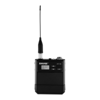
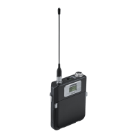
Shure U1/U1L Body-Pack UHF Transmitter
17
25C1021 (BG)
Service Procedures
Deviation Reference Voltage Adjustment
AUDIO ANALYZER
U4 RECEIVER
20 dB PAD
DC BLOCK
NOTE: DC VOLTAGES ARE PRESENT
AT MOST RF TEST POINTS. USE A
DC BLOCK ON THE RF SIGNAL
GENERATOR TO PROTECT
TEST EQUIPMENT.
U1 Transmitter Audio Analyzer
Power: +3 Vdc Measurement: AC level
Gain: Minimum; for JB models,
set to MAX
Output: 1 kHz
Filters:
Low-Pass (30 kHz): ON
High-Pass (400 Hz): ON
Figure 8. Deviation Reference Voltage Adjustment Test Set-Up
1. The U1 transmitter should be turned ON for this procedure.
2. Turn the rf signal generator OFF for this procedure.
3. For G and later board versions, adjust the audio analyzer for 1
kHz to get a level of –5.0 dBu (436 mV) at pin 7 of U201.
4. For F or earlier board versions, adjust the audio analyzer for
1 kHz to get a level of –5.0 dBu (436 mV) at pin 1 of U201.
5. On JB models, adjust the audio analyzer for 1 kHz to –61.0 dBu
at the input connector.
6. Connect the transmitter rf output to a U4 antenna connector
through a dc block and a 20 dB pad.
7. Connect the U4 unbalanced output to the audio analyzer’s input.
8. Adjust R243 until the audio analyzer reads the deviation
reference voltage, measured in the last test, from the
unbalanced output of the U4 receiver, ± 0.1 dB.
9. Turn OFF the 30 kHz low-pass filter and the 400 Hz high-pass
filter on the audio analyzer.
10. Disconnect the audio analyzer output from the U1 mic input.