Operating Instructions Chapter 1
ICR880/890
Notes on this document
8011325/XL85/2013-08-20 © SICK AG · Germany · All rights reserved · Subject to change without notice 7
1 Notes on this document
1.1 Purpose
This document provides instructions for technical staff on the installation and operation of
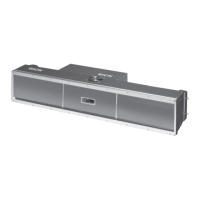
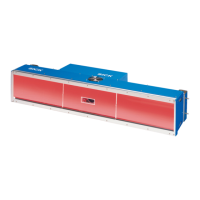
the Camera Systems in the ICR880/890 series with focus control and the following variants
of system components:
– System 1:
ICD880 Camera with standard lens (focal distance 80 mm (3.15 in)) and ICI890-x11xx
illumination (length 750 mm (29.5 in))
– System 2:
ICD890 Camera with standard lens (focal distance 135 mm (5.32 in)) and ICI890-
x10xx illumination (length 900 mm (35.4 in))
– System 3:
ICD890 Camera with standard lens (focal distance 135 mm (5.32 in)) and ICI890-
x00xx illumination (length 1,100 mm (43.3 in))
All systems comprise a version of the co-ordinating MSC800 Controller.
A summary of all available Camera System versions is shown in Chapter 3.1.3 Device ver-
sions, Page 20.
This document contains the following information about the Camera Systems:
Safety Information
Installation and electrical installation
Startup and configuration
Maintenance
Product features and functions
Troubleshooting
Replacing system components
Technical data
A step-by-step approach is taken for all tasks.
Important In this document the system components are referred to simplified terms, except where a
distinction of the variants is necessary:
ICR880 or ICR890 Camera System, simplified: Camera System
ICD800 or ICD890 Image Capture Device, simplified: Camera
ICI890 Image Capture Illumination, simplified: ICI890 Illumination
MSC800 Modular System Controller, simplified: MSC800
MLG Light Grid (Modular Light Grid), simplified: MLG Light Grid
VMS4xx/5xx Volume Measuring System, simplified: VMS4xx/5xx
SICK Open P
ortal for Application and Systems Engineering Tool, simplified:
SOPAS-ET Configuration Software
The register tabs for configuration of the Camera Systems and the MSC800 are re-
ferred to in the SOPAS-ET Configuration Software online help as "device pages".
1D codes generally mean bar codes also called linear codes.
2D codes generally mean stacked codes and matrix codes. Chapter 9 Technical data,
Page 81 lists the code types readable by the Camera System.
 Loading...