18
8 007 487/10-10-99 Technical Description • LGT © SICK AG • Safety Systems • Germany • All rights reserved
8 Technical Data of LGT Safety Light Grid
8 Technical Data of LGT Safety Light Grid
1
) A power supply unit with safeguarded isolation
(SEL V, PEL V circuit) must be used.
2
) The voltage must not exceed or fall below the
limit values.
Caution: In the event of high-energy overvoltages
between DC supply and PE potential (≥ 0.5 kV)
a switch to AC supply and/or insulated mounting
of the sensor strips is recommended. In case of
interference also lay the sensor cables isolated
from the interfering cable duct.
3
) Cannot be shortened.
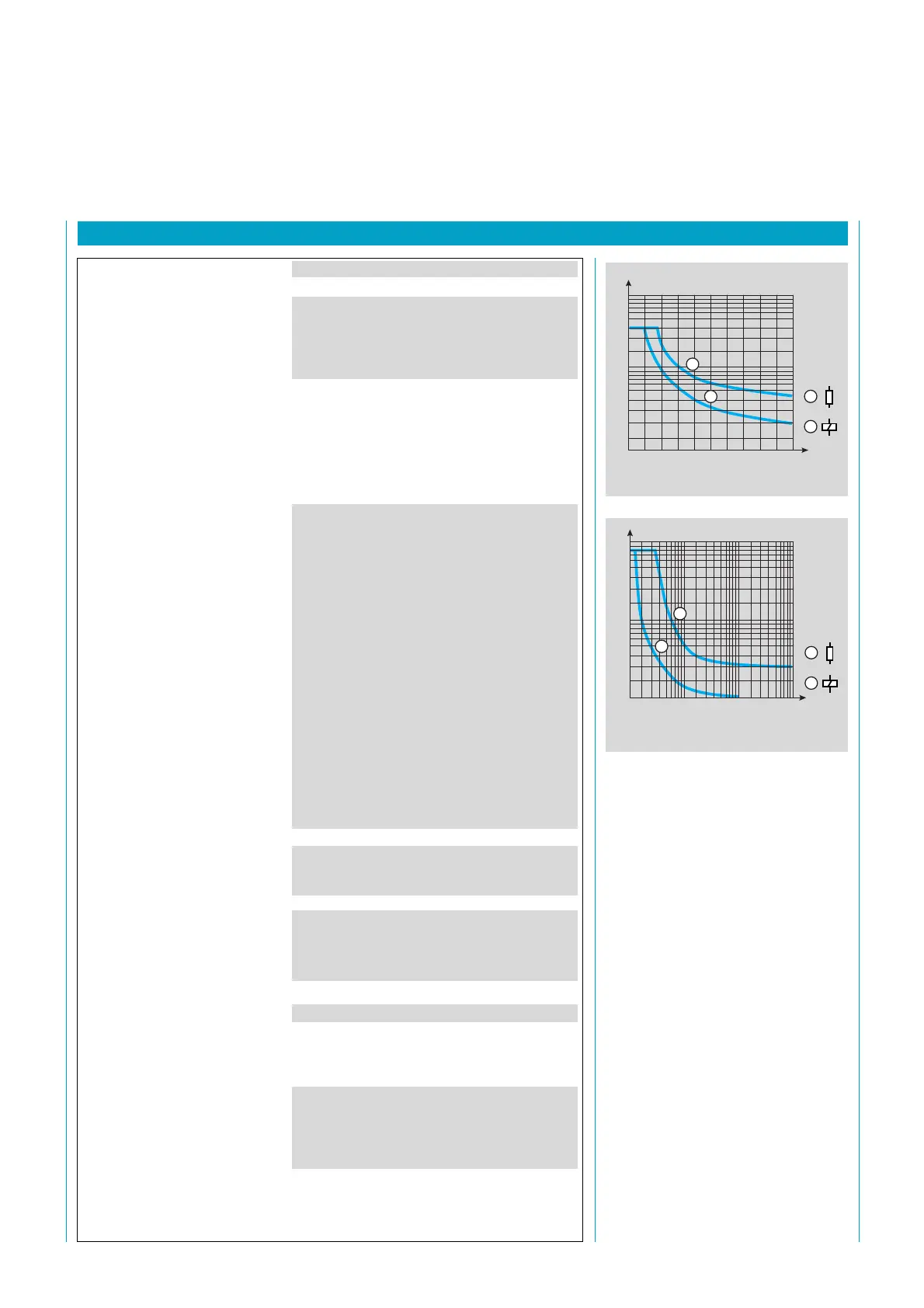
Main relay
1
1
2
2
V DC
A
500 100 150 200 250
10
1,0
0,1
1
1
2
2
VDC
A
10 100 300200
10
1,0
0,1
Auxiliary relay
min. typ. max.
General system data
Protective field height 150 mm 900 mm
Protective field width 0.1 m 6 m
Resolution 30 mm
Wave length of the sender 880 nm
Protection class 1
Enclosure rating
Light grid IP 65
Control unit IP 54
or IP 20 (for cabinet installation)
Operating mode with or without restart inhibit
Supply voltage U
V
1
)
DC 19.2 V 24 V 28.8 V
ripple
2
) 5 V
ss
or
AC 92 V 115 V 126.5 V
184 V 230 V 253 V
frequency 48 Hz 62 Hz
Power consumption 13 W
16 VA
Output
Main relay
resistive 4 A, 45 V DC
(see diagram)
inductive 4 A, 25 V DC
(see diagram)
Auxiliary relay
resistive 8 A, 55 V DC
(see diagram)
inductive 8 A, 15 V DC
(see diagram)
Protective zone status surge-proof
100 mA
U
V
– 2,5 V (HIGH) U
V
600 µA (I
Q
)
Dirt indicator surge-proof
100 mA
U
V
– 2.5 V (HIGH) U
V
600 µA(I
Q
)
Response time 50 ms
Length of connecting leads see 11.2 selection table
3
)
Operating modes 0.1 mm
2
1.5 mm
2
Operating data
Safety category type 2
Requirements pr EN 50100
Operating temperature range – 10 °C + 55 °C
Humidity range 15 % 95 %
Storage temperature range – 25 °C + 70 °C
Dimensions See 9 Dimensions
Housing colour Cadmium yellow, RAL 10-21
Vibrostability 5 g, 10 ... 55 Hz to IEC 68-2-6
Shock resistance 10 g, 16 ms acc. IEC 68-2-29
 Loading...