3
Stabilizer Operation and User guide version 2950-4 - 2018
1 1
2 2
4
3
5
6
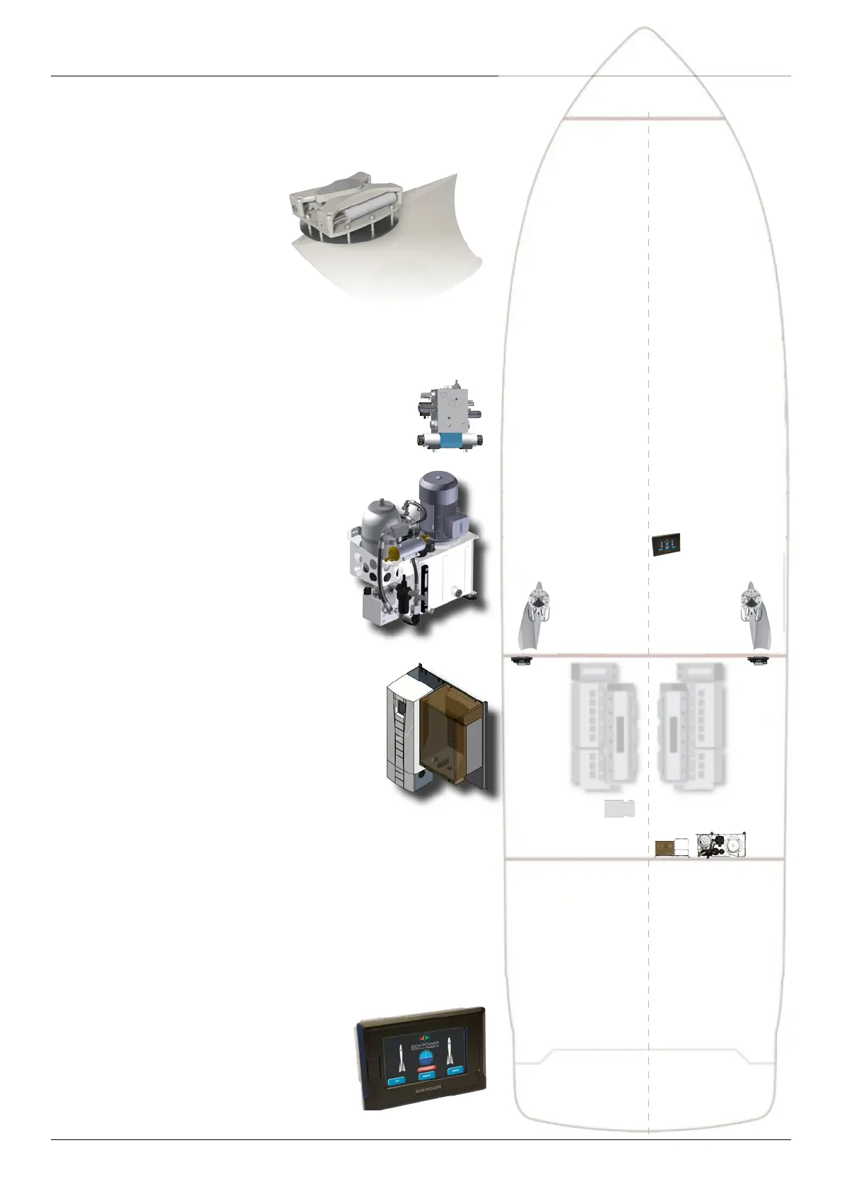
Typical component layout in the boat
1
The actuators and fins are
normally fit in the aft end of the liv-
ing area, usually the owners state-
room or bathroom & wardrobe.
The actuators are quiet so it is no
problem to have in living space
beneath the floor or furniture. The
fins wich is attached to each actua-
tor are working outside of the hull.
2
The proportional valves
(one for each actuator)
are placed outside of living space, in sound proofed
area.
3
The electrohydraulic powerpack
with tank, filtration and cooling is normally
placed in the engine room.
4
The controller / driver for the power-
pack
is located relatively close to the powerpack.
Thereby, often fitted above the powerpack/tank
on a wall. This contains a high voltage VFD so it
should be placed to ensure to be dry at all times.
5
The DC 24V electric or hydraulic cooling water pump
,
if fitted, is typically installed in an easily accesible and identified
position (because it often needs venting after the boat has been
on land) well below the waterline - close to the powerpack.
6
The main ECU
with sensors is placed on a bulkhead, central
in the boat. (In most cases)
7
The Control Panel
is placed on the dashboard(s) of the
yacht
7