© Arc Euro Trade Ltd, England 2012
- 11 -
-
-
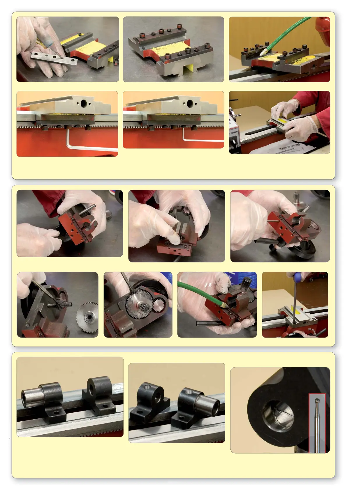
92. Loosen shear plate adjusting screws below the level of the plate and loosely fi t to saddle. 93. Oil bed and saddle and slide saddle onto bed.
103. Grease or oil pinion gear and shaft assembly 104. Oil 1/2 nut cam slots and dovetails. 105. Temporarily fi t apron to saddle.
Carry out all the following adjustments to both the
front and rear shear plates step by step.
94. Lightly pinch middle cap screw.
95. Screw in adjusting screws until just touching.
96. Slacken the middle cap screw.
97. Screw in both adjusting screws 1/2 turn.
98. Pinch up middle cap screw.
100. Check 1/2 nuts are correctly adjusted on apron
by operating lever.
106. The leadscrew brackets as they come on
the machine. Notice there is no means of
lubricating the bearing surfaces other than at
each end of the bracket.
101. Check there is no rock on the 1/2 nuts.
107. Drill oil holes through to the bore using a
centre drill.
102. Adjust the gib screws if necessary.
108. Finish off by cutting oil grooves in the bore
using a Dremel and a 3mm ball end burr
similar to the one shown in the inset.
(ARC code: 060-030-00310 - Carbide Burr 3mm Ball)
99. Test slide saddle up and down the bed. There
should be slight drag with no free play. Lightly
pinch up remaining cap screws checking after
each one and adjusting as required.
 Loading...