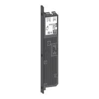
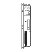
Connections Function
A, B, C, D
Terminal A/B = Data interface SI - RS 485
Terminal C = Output supply voltage - GND
Terminal D = Output supply voltage + 24 V DC
2, 3
Operating voltage
Terminal 2 = + 24 V DC
Terminal 3 = -- GND
4
External unlocking signal.
If +24 V DC is supplied to this terminal for ≥1 sec., then an opening cycle is performed in both modes of operation.
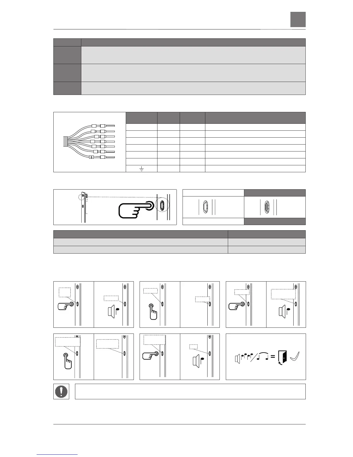
Wiring allocation
0
1
4
7
+
-
Cable
detection
Band
colour
Cable
colour
Function
0 black grey Switching between Day/Night mode of operation
1 brown yellow Switching between Day/Night mode of operation
4 yellow green External unlocking signal
7 violet pink Indicating door/lock status
--/3 blue brown Operating voltage (--) negative
+/2 red white Operating voltage (+) 24 V DC
white blue Shield
Set Day/Night adjustment
Day mode
Night mode
White LED
Blue LED
Switchover between Day and Night mode Press button just once
Day mode: E opening function, door is not locked LED lights up white
Night mode: Automatic locking when door closes LED lights up blue
Adjust magnetic sensor manually (only necessary if the multi-point lock does not lock when the
door is closed)
► ►
► ►
Manual activation via the lever handle or the cylinder lock only in case of shutdown of the motor of the
GENIUS2.1 PANIC multi-point lock as the locking process would otherwise be interrupted.
1 sec
1 x
1 sec
5x
Magenta
Turquoise
Blue or
white
Magenta
8 sec
1x
Turquoise
Flashes
Turquoise/White
3 sec
1x
Flashes
Turquoise/White
Flashes
Turquoise/Red
1 sec
3x
Flashes
Turquoise/Red
Blue
3 sec
1x
302.2017
KFV
GENIUS 2.1 A


 To Next Page