s
Product documentation 1D 3.8.en Rev. E, 10/13 page 29/42
4.3 Electric installation
4.3.1 Making the electrical connections
(cable terminal compartment for stator connection)
The electrical connections inside the machine are made at the factory, taken to the cable terminal
compartment for the stator connection (see text to dimension drawing) and subjected to an HV winding test.
To make the stator connections, open the cable terminal compartment and the marked earthing terminals in
the cable terminal compartment and the conductor clamp. The terminals are designed to receive cable lugs see
(
Fig. 13). Connect the supply lead in accordance with the main terminal diagram, pay attention to the right
direction of rotation (see text to dimension drawing). The conductors should make good electrical contact,
which entails the contact surfaces should be free from irregularities the contact surfaces should be metallic-
bright (i.e. treat the surfaces with a clean, mediumfine steel-wire brush, dirt and oxidation should be removed)
the contact surfaces should be greased with acid-free vaseline the connecting elements should be carefully
assembled and tightened with the specified torque (
Tab. 6).
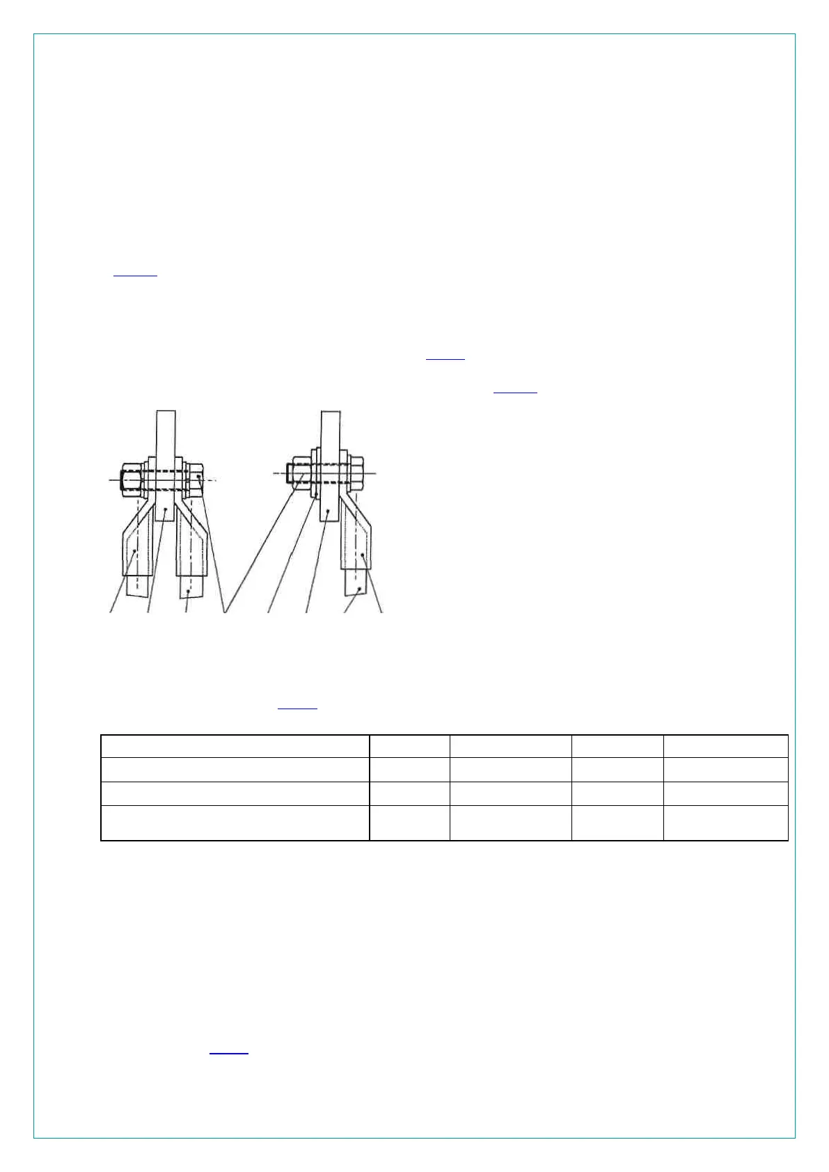
The factory recommends making the connections as shown in (
Fig. 13)
Fig. 13 Recommended stator terminal arrangement
The bolts are to be tightened with a torque wrench. The tightening torques for electrically conducting con-
nection bolts are shown in (
Tab. 6). Connections are provided in the terminal box for earthing the cable
sheaths (see dimension drawing). The connections and sealing ends should comply with the local regulations.
Size of connection elements M10 M12 M16 M20
Material St St St St
Strength class 8.8 8.8 8.8 8.8
Tightening torques in Nm 40 70 155 340
Tab. 6 Tightening torques for screwed electrical connections
The cable entry of the cable terminal compartment is closed off by a plate of insulating material (see dimension
drawing).
The holes required for entering the cables must be drilled during installation in accordance with the cable
clamps used.
The cable entry point must be suitably sealed on completion of cable installation.
Before closing the cable terminal compartment, check that the screwed electrical connections have been
made properly the inside of the cable terminal compartment is clean and free from trimmed-off ends of wiring
material the minimum air clearances are adhered to in accordance with the local regulations, taking account of
protruding ends of bolts and conductors unused cable entries are closed and their connecting elements are
securely screwed in.
As an example, (
Tab. 7) lists the minimum air clearances laid down in DIN EN 60079-7 (VDE 0170-6).
01
Incoming cable to stator terminal
02
Cable lug to DIN 46235
03
Terminal in terminal box (ready drilled to receive 16 mm or
20 mm dia bolt)
04
Fixing elements
Hexagonal bolt, DIN EN 24017 (ISO4017), 8.8-A-A3C
Hexagonal nut 6, DIN EN 24032 (ISO4032), 8-A-A3C
Spring washer , DIN 128, spring steel Washer, DIN 125, St-
A3C
05
Conical spring washer, DIN 6796, spring steel Washer,
SN 62501, St-A3C
02 03 01 04 05 03 01 02

 Loading...


