3.3 Remote Control Internal Features
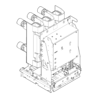
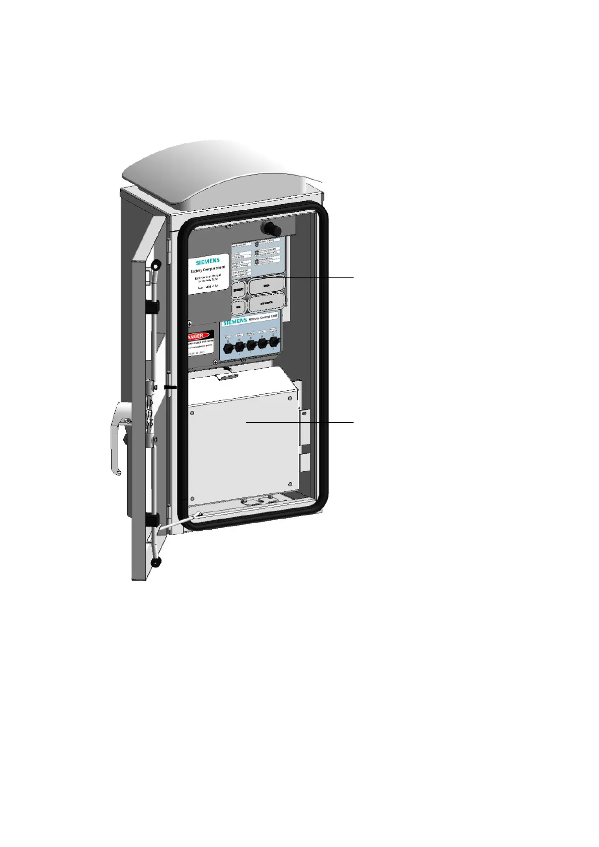
The RCU enclosure provides a protective shell for the electronics housing and radio tray as shown
in figure 4 below.
Fig. 4 Main Internal Elements
1 Electronics Housing
2 Radio Tray
3.3.1 Electronics Housing
The electronics housing contains the micro-processor, battery, power connection terminals, data
connection points and the user interface for the RCU. The RCU has a simple user interface for
operations and maintenance purposes. The RCU front panel is shown overpage in figures 5 and 6.
It has a number of LED indictors. The LEDs are normally off (to reduce power consumption) and
turn on automatically while the door is open as controlled by the position of the door switch.
After connection of a power supply the operator uses toggle switches to turn the RCU “ON”. The
LED indicator display panel provides feedback to the operator as to the function of the RCU and the
connections between RCU, switchgear and the SCADA system.