possible electric shock risk that could lead to serious injury or
death.
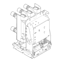
1 Active wire
2 Neutral wire
3 Insulation
Fig. 25 Mains Cable Details
5.7.2 Installation Process – Incoming Mains Connected to Electronics Housing
The mains cable should be connected according to the following process using wire of the correct
specification to ensure IP 3x rating is maintained for the terminal compartment.
1 The mains cable is fed through the cable gland on the RCU enclosure a suitable amount
to allow connection into the power supply compartment. The cable gland should be
tightened to clamp the mains cable.
2 Active and neutral of the mains cable are connected into the power supply compartment
terminal block and tightened in place. Ensure the correct wire is installed into the
matching terminal block.
3 Select the appropriate wire entry blanking plate from the various plates provided.
Minimise the clearance between the slot in the blanking plate and the external diameter
of the mains cable insulation.
4 The plastic cable barrier suitable for the mains cable (not the one for solar power supply)
is slid into place over the mains cable outer insulation.
5 Fit the power compartment cover and screw in place (torque 1.5Nm) using screw driver.
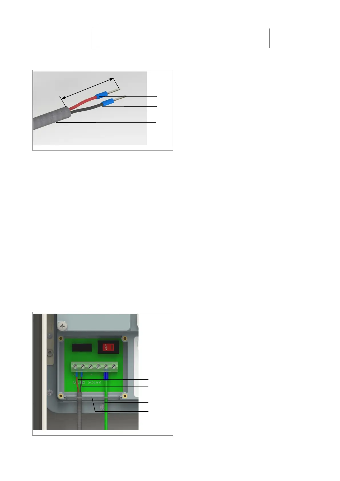
1 Active wire
2 Neutral wire
3 Earth wire
4 Wire entry blanking plate - mains
Fig. 26 Mains Cable Connection Details