10.5.2 Serial Interface
This is via the DB25 serial connector on the electronics compartment. Use of these signals is
protocol dependent. Refer to the relevant Protocol Manual for details. There are two options
for electrical signal levels:
1 RS232
2 DC: 3 V to 9 V logic level with respect to 0 V (battery negative). The voltage is
configurable and applies to all signals. The sense of each signal can be configured
separately (i.e. whether voltage high signals logic true or false).
When using the Serial Interface there is a Push-To-Talk (PTT) clean contact for operation of
some radios (max current 0.5 A, max voltage 20 V). When using the PTT output there are
configurable pre-transmit and post-transmit times (0 – 10 sec resolution 0.1 sec).
10.5.3 10/100baseT Data Interface
Connection is though the Ethernet RJ45 connector on the electronics compartment. If a
modem is being used, power can be supplied via the DB25 connector as described above.
The interface supports IPv4 and IP address allocation can be configured statically or via DHCP.
The RCU defaults to the following static allocation, which is useful for a direct connection to a
PC:
This interface is intended for use where DNP3 over IP is required. This implementation allows
a single master only, and supports TCP Listener and TCP Dual Endpoint types. Refer to “KMS-
0022 DNP3 Protocol Manual” for full configuration details.
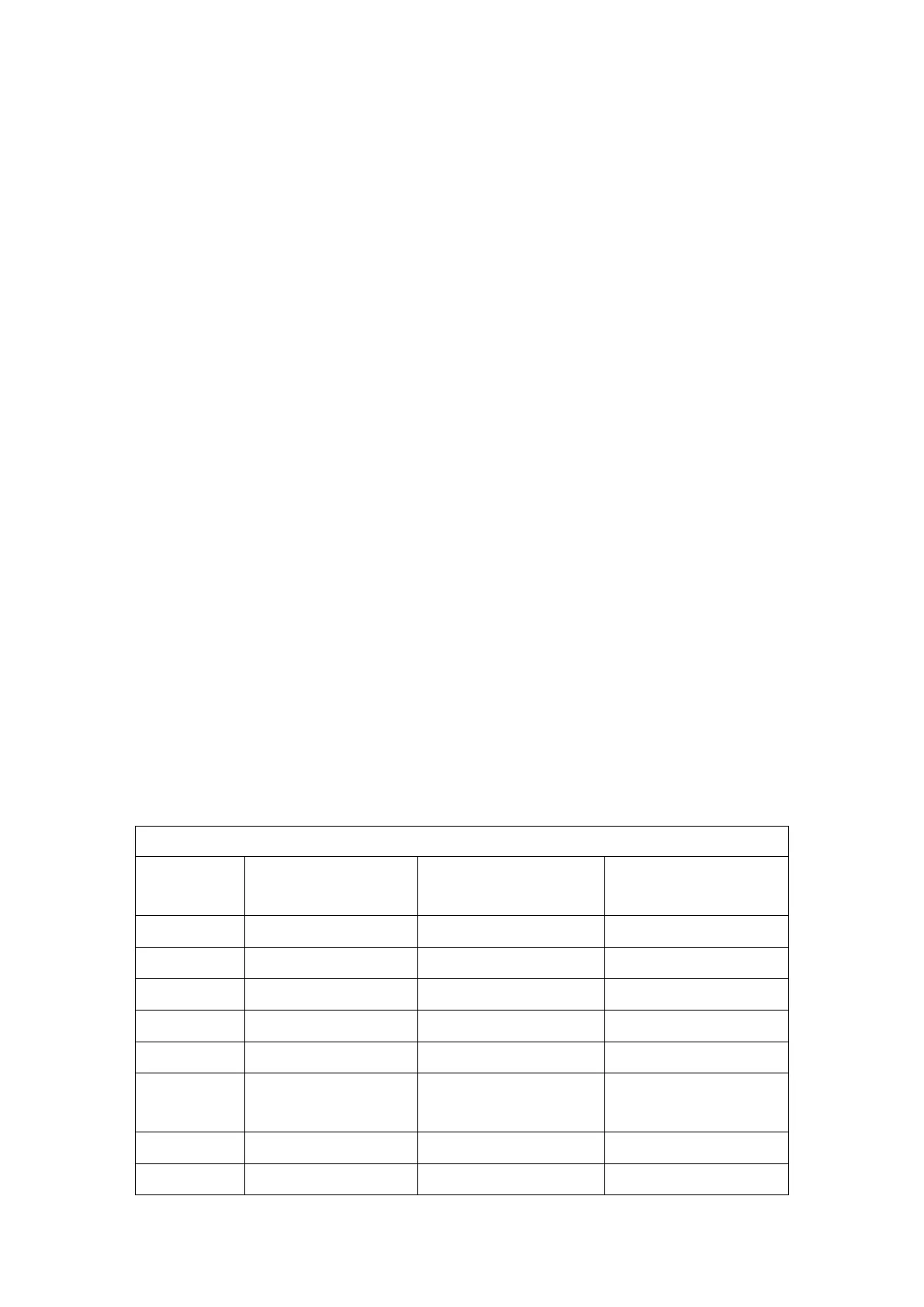
10.5.4 Serial Connector – DB25
The 25 way serial connector on the electronics compartment is female. The radio cable should
have a male connector to match. The table below lists the interface signals available on each
pin of the connector.
RCU Electronics
Input/Output
Radio Power
Supply Positive
Configured
DC: 3-9 V or battery