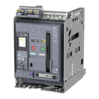
Overload Relays
3RB2 Solid-State Overload Relays
3RB20, 3RB21 for standard applications
20
Siemens · 2011
■
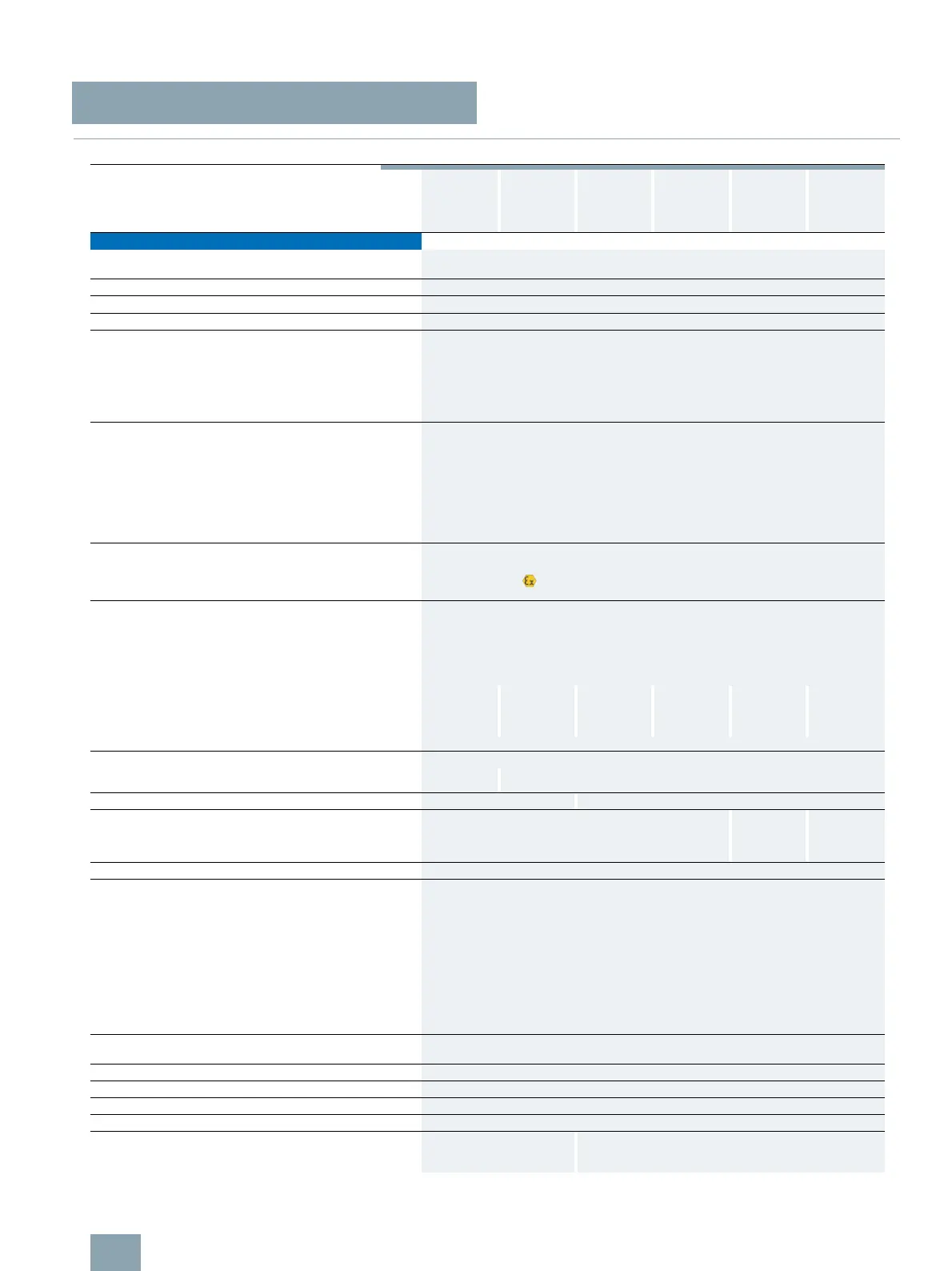
Technical specifications
1) On request.
2) S0 for 6 ... 25 A, CLASS 20,
I
emax
= 19 A;
S0 for 6 ... 25 A, CLASS 30,
I
emax
= 16 A.
3) 90 % for relay with current setting range 160 ... 630 A.
4) Terminal compartment: degree of protection IP00.
5) Signaling contact 97/98 in position "tripped": 4/11 g/ms.
Type 3RB20 16,
3RB21 13
3RB20 26,
3RB21 23
3RB20 36,
3RB21 33
3RB20 46,
3RB21 43
3RB20 56,
3RB21 53
3RB20 66,
3RB21 63
Size
S00 S0 S2 S3 S6 S10/S12
Width
45 mm 45 mm 55 mm 70 mm 120 mm 145 mm
General data
Trips in the event of Overload, phase failure, and phase unbalance
+ ground fault (for 3RB21 only)
Trip class acc. to IEC 60947-4-1 CLASS
10/20/5, 10, 20 and 30 adjustable (depending on the version)
Phase failure sensitivity
Yes
Overload warning
No
Reset and recovery
• Reset options after tripping Manual, automatic and remote RESET (depending on the version)
• Recovery time
- For automatic RESET
min.
Approx. 3 min
- For manual RESET
min.
Immediately
- For remote RESET
min.
Immediately
Features
• Display of operating state on device Yes, by means of switch position indicator slide
• TEST function
Yes, test of electronics by pressing the TEST button /
test of auxiliary contacts and wiring of control circuit
by actuating the switch position indicator slide /
self-monitoring
• RESET button
Yes
• STOP button
No
Explosion protection – safe operation of motors with
"increased safety" type of protection
EC type test certificate number acc. to
directive 94/9/EC (ATEX)
PTB 06 ATEX 3001 II (2) GD
Ambient temperatures
• Storage/transport °C -40 ... +80
•Operation °C
-25 ... +60
• Temperature compensation °C
+60
• Permissible rated current at
- Temperature inside control cabinet 60 °C,
stand-alone installation
%
100 100
2)
100 100 100 100 or 90
3)
- Temperature inside control cabinet 60 °C,
mounted on contactor
%
100 100
2)
100 100 70 70
- Temperature inside control cabinet 70 °C
%
1)
Repeat terminals
• Coil repeat terminal Yes Not required
• Auxiliary contact repeat terminal Yes Not required
Degree of protection acc. to IEC 60529 IP20 IP20
4)
Touch protection acc. to IEC 61140 Finger-safe Finger-safe,
for busbar
connection
with cover
Finger-safe
with cover
Shock resistance with sine acc. to IEC 60068-2-27 g/ms
15/11
5)
Electromagnetic compatibility (EMC)
– Interference immunity
• Conductor-related interference
- Burst acc. to IEC 61000-4-4
(corresponds to degree of severity 3)
kV
2 (power ports), 1 (signal ports)
- Surge acc. to IEC 61000-4-5
(corresponds to degree of severity 3)
kV
2 (line to earth), 1 (line to line)
• Electrostatic discharge acc. to IEC 61000-4-2
(corresponds to degree of severity 3)
kV 8 (air discharge), 6 (contact discharge)
• Field-related interference acc. to IEC 61000-4-3
(corresponds to degree of severity 3)
V/m 10
Electromagnetic compatibility (EMC)
– Emitted interference
Degree of severity B acc. to EN 55011 (CISPR 11) and EN 55022 (CISPR 22)
Resistance to extreme climates – air humidity %
100
Dimensions
See dimensional drawings
Installation altitude above sea level m
Up to 2000
Mounting position
Any
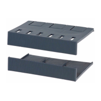
Type of mounting
Direct mounting/stand-alone
installation with terminal bra-
cket
Direct mounting/stand-alone installation