EasyManua.ls Logo

Siemens 3TL81 - User Manual

Siemens 3TL81
20 pages
Print Icon
To Next Page IconTo Next Page
Loading...
13ZX1812-TL80-0AN7 / 9229 9870 174 0G
2003-03-12
Betriebsanleitung/Operating Instructions Bestell-Nr./Order No: 3ZX1812-0TL80-0AN7 / 9229 9870 174 0G
Vakuum-Hochspannungsschütze 3TL81 7,2 kV / 400 A
High-voltage vacuum contactors 3TL81
Fig. 1 Dreipoliges Vakuum-Hochspannungsschütz 3TL81
Triple-pole high-voltage vacuum contactor 3TL81
WARNING
Parts of the high-voltage vacuum contactor
are under hazardous voltage and under spring
pressure.
Maintenance by qualified personel only !
Follow the operation instructions !
Non-compliance can result in death, servere
personnel injury and substantial property dam-
age !
WARNUNG
Teile der Vakuum-Hochspannungsschütze
stehen unter gefährlicher elektrischer Span-
nung sowie unter Federdruck.
Instandhaltung nur durch Fachpersonal !
Beachten Sie die Betriebsanleitung !
Bei Nichtbeachtung können erheblicher Sach-
schaden, schwere Körperverletzung oder Tod
die Folge sein !
Alle Rechte vorbehalten. All rights reserved.
© Siemens AG 1996
Bestell-Nr./Order No.: 3ZX1812-0TL80-0AN7 / 9229 9870 174 0G
Bestell-Ort/Place of Order: PTD M C P1 Log Berlin
Printed in the Federal Republic of Germany
AG 03.2004 Kb De-En

Table of Contents

Question and Answer IconNeed help?

Do you have a question about the Siemens 3TL81 and is the answer not in the manual?

Overview

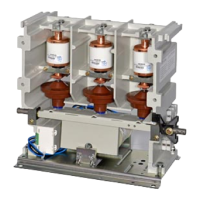
The Siemens 3TL81 high-voltage vacuum contactor is a switching device designed for high switching frequencies and unlimited ON duration in AC circuits. It is suitable for various applications, including three-phase motors, transformers, capacitors, and resistive loads, as well as for motor reversal duty. The contactor features a solenoid-operated mechanism that can be actuated by either AC or DC current.

Function Description:

The 3TL81 vacuum contactor is primarily used for making and breaking electrical connections in high-voltage systems. Its design, with a chopping current of only 0.6 A, makes it particularly well-suited for switching inductive loads. The contactor is built as a non-enclosed type with a degree of protection IP00 according to DIN/VDE 0470 Part 1 and IEC 144. It is designed for use in buildings with poor thermal insulation or low thermal capacity, whether heated or cooled, and can tolerate occasional condensation (approximately once a month for 2 hours).

Important Technical Specifications:

  • Rated Voltage (Ue): 7.2 kV
  • Rated Frequency: 50-60 Hz
  • Rated Operating Current (Ie):
    • 400 A at ambient temperature up to +55 °C
    • 360 A at ambient temperature up to +65 °C
  • Initial Symmetrical Short-Circuit Current: 20 kA (with a maximum opening time of 120 ms)
  • Peak Short-Circuit Current: 40 kA
  • Maximum Cut-Off Current (ID) with HV-HRC Fuses: 50 kA
  • Rated Short-Time Withstand Current (1s rms value): 8 kA
  • Capacitor Circuits Rated Operating Current: 250 A
  • Permissible Switching Frequency (AC/DC operation): 1200 operating cycles per hour
  • Mechanical Service Life of the Contactor: 1 x 10^6 operations
  • Mechanical Service Life of the Vacuum Interrupter: 0.25 x 10^6 operations
  • Electrical Service Life of the Vacuum Interrupter (at rated current): 0.25 x 10^6 operations
  • Endurance in Storage: 20 years
  • Permissible Ambient Temperature:
    • Storage: -40 to +65 °C
    • Operation: -5 to +65 °C (1 x 10^6 operating cycles)
    • Operation: -5 to -25 °C (0.5 x 10^6 operating cycles)
  • Rated Input of the Control Circuit (AC/DC operation):
    • When closing: 600 W
    • When holding: 90 W
  • Opening Times (at a function of the economy circuit):
    • 110-250 V: 325 ± 75 ms
    • 24-60 V: 200 ± 60 ms
  • Dielectric Strength:
    • Rated impulse withstand voltage (against earthed parts and between phases): 60 kV
    • Rated impulse withstand voltage (across the contact gap): 40 kV
    • Rated power frequency withstand voltage 50 Hz (rms value) (against earthed parts and between phases): 20 kV
    • Rated power frequency withstand voltage 50 Hz (rms value) (across the contact gap): 20 kV
  • Permissible Site Altitude: 500 m below to 2000 m above sea level (with correction factor for insulating capacity above 1000 m).
  • Conductor Cross Sections (Main Conductors): M10 terminal screw, 50-240 mm² for stranded wire with cable lug. Copper bar 30 x 5 mm, aluminum bar 20 x 10 mm.
  • Auxiliary Contacts: 2 NO + 2 NC or 4 NO + 4 NC available.
  • Rated Operating Current for Auxiliary Contacts (AC 11): 10 A (up to 220 V), 4 A (500 V), 2 A (600 V).
  • Rated Operating Current for Auxiliary Contacts (DC 11): 10 A (24 V), 5 A (110 V), 0.9 A (125 V), 0.45 A (220 V), 0.25 A (440 V), 0.2 A (600 V).
  • Conductor Cross Sections (Auxiliary Contacts): 0.6-4.0 mm² for solid conductors, 0.5-2.5 mm² for finely stranded conductors with end sleeves.
  • Degree of Protection: IP00.

Usage Features:

The vacuum contactor requires short-circuit protection, as it is not designed to switch short-circuit currents. HV HRC fuses are recommended for this purpose. When coordinating HV HRC fuses with motor circuits, the fuse's time/current characteristic must be to the right of the motor starting current, and its rated current must exceed the motor's operating current. If two fuses are connected in parallel, their impedance values should be almost equal. The vacuum contactor must be switched off if the fuses blow, which requires a suitable device actuated by the striker pin of the HRC fuse. For "Class E2-Controller" applications, SIEMENS fuses of type 3GD1 150-UD (7.2 kV/250 A) or comparable alternatives are specified.

Installation:

The contactor can be mounted vertically or horizontally using M10 stud bolts or M10 hex. hd. screws. It is crucial to avoid twisting the bottom plate of the contactor and to use spacer rings if the bottom plate does not rest squarely. Busbars and cable lugs should be installed off-load to prevent undue stress on the primary conducting paths. Conductors up to 30 mm width can be connected. For copper conductors, brush until bright and apply a thin film of vaseline. For aluminum conductors, the plated surface finish of the terminals must be removed before brushing and applying vaseline, unless they are galvanized or silver-plated. The contactor causes vibrations during switching, so it should not be mounted on vibration dampers. Earthing can be achieved via an M12 earthing screw with flat copper pieces, stranded copper conductor, or hot-dip galvanized steel straps, or by mounting on an earthed steel support frame. Auxiliary switches are connected directly and must not be used for activating mechanical latching or interrupting the closing command for the vacuum contactor; an external contactor relay must be used for these functions.

Maintenance Features:

The vacuum contactor is maintenance-free until the end of its mechanical service life (1 million switching operations). For repair work, the contactor must be removed from the switchboard. Installation of spare parts and accessories must follow the relevant operating instructions. To maintain insulating capacity, insulating components and external contactor parts must be cleaned with a damp cloth using warm water and a mild liquid household detergent. All maintenance, repair, and conversion work must be carried out by specially trained personnel in accordance with operating instructions and safety regulations, including the "five safety rules" (DIN EN 50110, Part 1 + 2). Before starting any work, the power supply must be switched off. Windings and terminals must not be touched if the power supply is not disconnected, as non-observance can result in death or serious personal injury.

Siemens 3TL81 Specifications

General IconGeneral
BrandSiemens
Model3TL81
CategoryIndustrial Equipment
LanguageEnglish

Related product manuals