A5E01070445A-02 Last update: 01 April 2011
Order No.: 3ZX3012-0TS30-0AY0
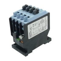
Contactor
3TS29, 3TS30, 3TS31, 3TS32
DIN VDE 0660, IEC 60947-4-1, Q/320500 SMS 009, GB14048.4
Operating Instructions
English
For dimension drawings (dimensions in mm) see:
Snap onto 35 mm standard mounting rail to DIN EN 50022 or fix on a plain surface
with two M4 screws. With screw mounting, always use plain washers and spring
washers. Cover the contactors during installation if foreign particles, such as swarf,
can fall onto them. Install contactors in a housing if they are exposed to dirt, dust or
aggressive atmospheres.
For permissible mounting positions see:
The terminal screws can be tightened with a power screwdriver.
Screwdriver blade width: 5 to 6 mm.
Permissible Conductor Cross-sections:
Use 75 °C copper wire only.
For circuit diagrams and positions of connection terminals see Fig. III。
Observe operating voltage (see rating plate of magnet coil).
The operating state of the contactor is shown at the position indicator; see Fig. IV.
.
Maintenance
The following components can be replaced:
magnet coil, single-pole auxiliary contact block 3TX3.
For Order No. see Catalog NSK.
Only use of original spare parts ensures the operational safety of contactors.
Cleaning
Remove dust by suction.
Auxiliary contact block
For replacement see Fig. V.
Magnet coil
For coil replacement see Fig. VI:
Ensure that the pole faces of the magnet coil are clean. Do not use grease solvents
or sharp objects for cleaning.
Weight:
Permissible ambient temperature:
Main circuit
Short-circuit protection:
Auxiliary circuit
Short-circuit protection:
Auxiliary contact block 3TX3
Short-circuit protection:
For further data and accessories see Catalog IC15.
Read and understand these instructions before installing,
operating, or maintaining the equipment.
DANGER
Hazardous voltage.
Will cause death or serious injury.
Turn off and lock out all power supplying this device before
working on this device.
CAUTION
Reliable functioning of the equipment is only ensured with
certified components.
Mounting
Fig. Ia AC operation
Fig. Ib DC operation
Fig. IIa AC operation
Fig. IIb DC operation
Connection
Solid
2 x 0.5 to 1 mm
2
2 x 1 to 2.5 mm
2
Finely stranded with end sleeve
2 x 0.75 to 2.5 mm
2
AWG wires
2 x AWG 18 to 12
Tightening Torque standard type 0.8 to 1.4 Nm
Tightening Torque auxiliary contact block 0.8 to 1.1 Nm
- Fig. IIIa 1NO
- Fig. IIIb 1NC
- Fig. IIIc without auxiliary contacts
Operation
When the system voltage is applied and the load is connected, do not
operate the contactor by pressing down the contact carrier.
Fig. VIa AC coil
Fig. VIb DC coil
Technical Data
AC operation approx. 370 g
DC operation approx. 580 g
operation -25 °C to +55 °C
storage -50 °C to +80 °C
Rated insulation voltage U
i
AC 690 V
Rated Insulation current I
e
/ AC-1 (55°C)
25 A
Rated operational voltage
Motor rating P
N
/AC-3
3TS29 3TS30 3TS31 3TS32
- 230 V kW 1.5 2.4 3.3 4
- 240 V kW 1.5 2.6 3.6 4
- 400 V kW 2.2 4 5.5 7.5
- 415 V kW 2.2 4 5.5 7.5
- 500 V kW 3 5.5 7.5 9
- 690 V kW 4 5.5 7.5 11
Degree of protection to DIN VDE
0660 / IEC 60947-4-1
Fuse-links Duty class gL (gG)
3TS29, 3TS30 3TS31, 3TS32
- assinment type 1 A 32 32
- assignment type 2 A 20 25
- non-welding I
k
≥ 100 x I
e
A10 10
- Circuit-breaker (C-char) A 16 25
Rated operating voltage Rated operating current I
e
/ AC-15 / AC-11
- 230 V / 220 V A 10
- 240 V A 10
- 400 V / 380 V A 6
-415V A 4
-500V A 4
- 690 V / 660 V A 2
Rated operating voltage Rated operating current I
e
/ DC-13 / DC-11
-24V A 10
-48V A 5
- 110 V A 0.9
- 220 V A 0.45
- 440 V A 0.25
- 600 V A 0.2
Fuse-links NEOZED and DIAZED, gL (gG) A 16
Circuit-breaker, C-char. A 10
Rated operating voltage Rated operating currentI
e
/ AC-15 / AC-11
- 230 V A 5.6
- 400 V A 3.8
- 500 V A 2.5
- 690 V A 1.8
Rated operating voltage Rated operating currentI
e
/ DC-13 / DC-11
-24V A 10
-48V A 4.6
- 110 V A 0.8
- 220 V A 0.2
- 440 V A 0.11
- 600 V A 0.08
Fuse-links NEOZED and DIAZED, gL (gG) A 16
Circuit-breaker, C-char. A 10
**Footnote: According to IEC 60947 / VDE 0660, the types of protection mean:
"Assignment type 1": Short circuits can cause damage to the contactors making replacement of the equipment necessary.
"Assignment type 2": Easily separable contact welding but no other damage.