EasyManua.ls Logo

Siemens 3VA1 100 Series - User Manual

Siemens 3VA1 100 Series
4 pages
Print Icon
To Next Page IconTo Next Page
Loading...
s
DE GEFAHR
Gefährliche Spannung. Lebensgefahr oder schwere Verletzungsgefahr.
Vor Beginn der Arbeiten Anlage und Gerät spannungsfrei schalten. Die Installations- und Wartungsarbeiten an
diesem Gerät dürfen nur von einer autorisierten Elektrofachkraft ausgeführt werden.
EN DANGER
Hazardous voltage. Will cause death or serious injury.
Turn off and lock out all power supplying this device before working on this device. Installation and mainte
-
nance work on this device may only be carried out by an authorized electrician.
FR DANGER
Tension électrique. Danger de mort ou risque de blessures graves.
Mettre hors tension avant d’intervenir sur l’appareil. Les travaux d'installation et d'entretien de cet appareil
doivent uniquement être réalisés par une personne qualifiée en électricité.
ES PELIGRO
Tensión peligrosa. Puede causar la muerte o lesiones graves.
Desconectar la alimentación eléctrica antes de trabajar en el equipo. Las tareas de instalación y mantenimiento
de este equipo solo debe llevarlas a cabo un electricista autorizado.
IT PERICOLO
Tensione pericolosa. Può provocare morte o lesioni gravi.
Scollegare l’alimentazione prima di eseguire interventi sull'apparecchiatura. L'installazione e la manutenzione di
questo apparecchio devono essere effettuati solo da un elettrotecnico autorizzato.
PT PERIGO
Tensão perigosa.Perigo de morte ou ferimentos graves.
Desligue a alimentação elétrica e proteja contra o religamento, antes de iniciar o trabalho no equipamento. Os
trabalhos de instalação e manutenção neste equipamento somente podem ser realizados for eletricistas autor
-
izados.
TR TEHLİKE
Tehlikeli gerilim. Ölüm tehlikesi veya ağır yaralanma tehlikesi.
Çalışmalara başlamadan önce, sistemin ve cihazın gerilim beslemesini kapatınız. Bu cihazın montajı ve bakımı
yalnız yetkili bir elektrik teknisyeni tarafından yapılmalıdır.
РУ ОПАСНО
Опасное напряжение. Опасность для жизни или возможность тяжелых травм.
Перед началом работ отключить подачу питания к установке и к устройству. Работы по монтажу и техни
-
ческому обслуживанию данного устройства должны производиться уполномоченным специалистом по
электротехнике.
РL ZAGROŻENIE
Niebezpieczne napięcie. Niebezpieczeństwo poważnych obrażeń lub utraty życia.
Przed rozpoczęciem prac wyłączyć zasilanie instalacji i urządzenia energią elektryczną. Prace instalacyjne i kon
-
serwacyjne na tym urządzeniu może przeprowadzać wyłącznie posiadający odpowiednie kwalifikacje elektryk.
中文 危险
危险电压。可能导致生命危险或重伤危险。
操作设备时必须确保切断电源。 该设备的安装和维护工作仅能由具备专业资格的 电工完成。
A5E03472775251-03 Last Update: 19 May 2015
3ZW1012-0VA01-8BA0
Technical Support: Internet: http://www.siemens.com/lowvoltage/technical-support
Betriebsanleitung
Operating Instructions
Instructions de service
Instructivo
Istruzioni operative
Instruções de Serviço
İşletme kılavuzu
Руководство по эксплуатации
Instrukcja obsługi
使用说明
Schienenverlängerung 3VA1 / 3VA2 100...630A
Rail extension 3VA1 / 3VA2 100...630A
Prolongement de barres 3VA1 / 3VA2 100...630A
Prolongación de barras 3VA1 / 3VA2 100...630A
Prolunga sbarre 3VA1 / 3VA2 100...630A
Extensão de trilhos 3VA1 / 3VA2 100...630A
Ray uzatması 3VA1 / 3VA2 100...630A
Удлинение шин 3VA1 / 3VA2 100...630A
Przedłużenie szyny 3VA1 / 3VA2 100...630A
母线延长件 3VA1 / 3VA2 100...630A
3VA9... - 0Q.00
IEC 60947
Question and Answer IconNeed help?

Do you have a question about the Siemens 3VA1 100 Series and is the answer not in the manual?

Overview

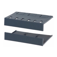
This document describes the Siemens 3VA1 / 3VA2 100...630A rail extension, a component designed to extend the busbar system for Siemens 3VA molded case circuit breakers (MCCBs). The rail extension is crucial for adapting the MCCB installation to various enclosure depths or busbar configurations, ensuring proper electrical connection and mechanical stability.

Function Description

The rail extension serves as an intermediary component, extending the connection points of 3VA1 and 3VA2 series MCCBs to align with existing busbar systems or to create custom busbar arrangements. It facilitates the connection of MCCBs with current ratings from 100A to 630A. The extensions are available in different pole configurations (1p, 2p, 3p, 4p) to match the MCCB and busbar requirements.

The primary function is to bridge the physical gap between the MCCB terminals and the main busbars, allowing for flexible installation within various panelboard or switchboard designs. This is particularly useful when the MCCB's standard terminal position does not directly align with the busbar system due to space constraints, different busbar depths, or specific panel layouts. By providing an extended connection, the rail extension ensures a secure and reliable electrical path while maintaining the necessary clearances and insulation.

The design incorporates features for robust mechanical attachment to both the MCCB and the busbar, ensuring stability under operational conditions, including short-circuit forces. The various types of extensions (e.g., "Montage extern" for external mounting, "Anschluss" for connection) indicate different installation methods and configurations, catering to a wide range of application scenarios.

Important Technical Specifications

The manual provides detailed specifications for different current ratings and MCCB series (3VA1 and 3VA2), including dimensions and torque values.

Current Ratings:

  • 3VA1: 100/160A, 250A
  • 3VA2: 100/160/250A, 400/630A

Pole Configurations:

  • 1p (1-pole)
  • 2p (2-pole)
  • 3p (3-pole)
  • 4p (4-pole)

Dimensions (Wmax, T, Lmin, H, Ø): These dimensions vary significantly depending on the specific rail extension type, current rating, and pole configuration. For instance, for a 3VA1 100/160A external mounting extension, Wmax is 22mm, T is 1-8mm, Lmin is 10mm, H is 12mm, and the diameter (Ø) for the screw is 6.6mm. For a 3VA2 400/630A external mounting extension, Wmax is 40mm, T is 2-12.5mm, Lmin is 15mm, H is 20mm, and the diameter (Ø) is 11mm. Similar variations apply to connection-type extensions.

Recommended Torque Values (Nm): The manual specifies torque values for tightening the connections. For example, for 3VA1 100/160A, the torque is 5 Nm for smaller connections and 8 Nm for larger ones. For 3VA2 400/630A, the torque can be as high as 20 Nm or 30 Nm, depending on the connection point. These torque values are critical for ensuring a secure electrical connection and preventing overheating or loose contacts. The "Nm -> MCCB" indication suggests that these torque values are specifically for the connection to the MCCB terminals.

Busbar Dimensions (for "Anschluss" type): The manual details compatible busbar dimensions, such as "2... 10 x 15.5 mm x 0.8 mm", "2... 8 x 20 mm x 1 mm", and "2... 8 x 24 mm x 1 mm". These specifications ensure compatibility with standard busbar systems.

Usage Features

The rail extension is designed for ease of installation and adaptability, offering several key usage features:

  • Versatile Pole Configurations: Available in 1p, 2p, 3p, and 4p versions, allowing it to be used with a wide range of MCCBs and busbar systems. The "Scope of delivery" section indicates that for 2P, 1x extension is provided; for 3P, 2x; and for 4P, 3x, implying that multiple extensions are used to cover all poles for multi-pole MCCBs.
  • Compatibility with 3VA1 and 3VA2 MCCBs: Ensures a broad application range across Siemens' 3VA series of molded case circuit breakers.
  • Multiple Mounting Options: The manual illustrates "Montage extern" (external mounting) and "Anschluss" (connection) types, indicating different methods of integration into the electrical panel. External mounting typically involves attaching the extension directly to the MCCB and then connecting to the busbar, while connection types might involve more direct busbar integration.
  • Clear Installation Steps: The visual instructions, including "click" and numbered steps, guide the installer through the process, making it intuitive. The "click" sound often indicates a secure mechanical engagement.
  • Tool Requirements: The manual specifies necessary tools, including wrenches (SW 10, SW 13, SW 16, SW 18) and a torque wrench (cal. ISO 6789), highlighting the importance of using appropriate tools for correct installation and tightening.
  • Robust Connection: The design aims for a secure and stable electrical connection, critical for high-current applications. The specified torque values are essential for achieving this reliability.
  • Space Optimization: By allowing flexible positioning of MCCBs relative to busbars, these extensions can help optimize space within electrical enclosures.

Maintenance Features

While the rail extension itself is a passive component and typically requires minimal direct maintenance, its proper installation is crucial for the overall system's reliability and safety. The maintenance considerations are primarily related to the initial installation and periodic checks of the connections:

  • Initial Installation Quality: The emphasis on precise torque values (e.g., "Nm -> MCCB") and the use of calibrated tools (cal. ISO 6789) during installation are critical for long-term reliability. Correct tightening prevents loose connections, which can lead to increased resistance, overheating, and potential fire hazards.
  • Periodic Inspection: As part of routine electrical system maintenance, the connections involving the rail extensions should be periodically inspected. This includes checking for any signs of loosening, corrosion, or overheating (discoloration of materials).
  • Authorized Personnel Only: The safety warnings (e.g., "Hazardous voltage. Will cause death or serious injury.") explicitly state that installation and maintenance work must only be carried out by authorized electricians. This ensures that personnel with the necessary expertise and safety training handle the equipment, minimizing risks.
  • De-energization Requirement: Before any work on the device, the system must be de-energized and locked out. This is a fundamental safety practice to prevent electrical shock.
  • Durability: The components are designed for industrial environments, implying a certain level of durability and resistance to environmental factors, reducing the need for frequent replacement.
  • Technical Support: The provision of an Internet link for technical support (http://www.siemens.com/lowvoltage/technical-support) indicates that resources are available for troubleshooting or guidance, should any issues arise during the lifespan of the product.

In summary, the Siemens 3VA1 / 3VA2 rail extension is a vital accessory for flexible and safe integration of MCCBs into various electrical distribution systems. Its design prioritizes secure connections, ease of installation, and compatibility, all while adhering to strict safety standards.

Siemens 3VA1 100 Series Specifications

General IconGeneral
BrandSiemens
Model3VA1 100 Series
CategoryIndustrial Equipment
LanguageEnglish

Related product manuals