Do you have a question about the Siemens 3VF5 211-1BM41-0AN1 and is the answer not in the manual?
| Rated voltage (Ue) | 690 V |
|---|---|
| Rated voltage | 690 V |
| Rated operational voltage | 690 V |
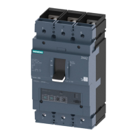
| Number of poles | 3 |
| Protection class | IP20 |
| Connection type | screw connection |
| Design of the operating mechanism | Rotary handle |
| Size of circuit-breaker | 3VF5 |
| Type of release | Thermomagnetic |
| Mounting | Fixed |
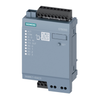
Details the 3VF circuit-breaker's design, operational principles, and PROFIBUS-DP communication.
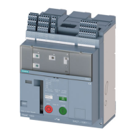
Describes the 3WN6 circuit-breaker's design and operational modes, including communication.
Outlines the step-by-step process for connecting the 3WN6 to a PROFIBUS-DP system.
Explains software blocks for SIMATIC S5/S7 integration with 3WN6 communication functions.
Describes the operational mode and design of 3WN1/3WS1 circuit-breakers with communication capabilities.
Details the step-by-step process for connecting 3WN1/3WS1 to a PROFIBUS-DP system.