EasyManua.ls Logo

Siemens 3VF Series User Manual

Siemens 3VF Series
114 pages
To Next Page IconTo Next Page
Page #1 background imageLoading...
Page #1 background image
Communication System Manual 3VF, 3WN, 3WS Circuit-Breakers
Version 1.0 (05/98) Copyright Siemens AG 1998. All rights reserved.
1
Contents
1 INTRODUCTION 4
1.1 Contents of this manual 4
1.2 Explanation of terms and advantages of "communication" 4
1.3 Explanation of terms "PROFIBUS" and "PROFIBUS-DP" 5
1.4 The open world of PROFIBUS-DP communication 6
2 3VF CIRCUIT-BREAKERS 7
2.1 Design and mode of operation 7
2.1.1 Communication via PROFIBUS-DP 7
2.1.2 Data exchange 8
2.1.3 Hardware and software connections of 3VF 10
2.1.4 Connecting 3VF to the communication system 12
2.1.5 Selection and ordering data 17
2.1.6 Parameter file 19
2.2 Technical data 25
2.3 Supplementary literature on 3VF communication 25
3 3WN6 CIRCUIT-BREAKERS 26
3.1 Mode of operation and design 26
3.1.1 General mode of operation of 3WN6 circuit-breaker communication via PROFIBUS-DP 26
3.1.2 Hardware and software requirements 26
3.2 Bus connection functionality 28
3.3 Procedure for connection to communication system 31
3.4 Displaying the data in the 3WN6 circuit-breaker 37
3.4.1 Addressing the 3WN6 functions on PROFIBUS-DP: 37
3.4.2 List of acyclic 3WN6 messages on PROFIBUS-DP 39
3.4.3 List of cyclical 3WN6 data traffic on PROFIBUS-DP 52
3.4.4 Examples of (acyclic) message requests: 54
3.4.5 Time response of data traffic 55
3.5 Description of software block required for utilizing communication functions
with SIMATIC S5 and S7 59
3.5.1 CPU and DP master types 59
3.5.2 Displaying data in PROFIBUS-DP 59
3.5.2.1 Parameterization 59
3.5.2.2 Configuration 59
3.5.2.3 Diagnostics 60
3.5.2.4 Data 60
3.5.3 STEP 5 program 63
3.5.3.1 Brief outline of software block tasks 63
3.5.3.2 Preparing to use the software block 63
3.5.3.3 General information and adaptations 63

Table of Contents

Question and Answer IconNeed help?

Do you have a question about the Siemens 3VF Series and is the answer not in the manual?

Siemens 3VF Series Specifications

General IconGeneral
Rated Current (In)16 A to 1600 A
Rated Voltage (Ue)Up to 690 V AC
StandardsIEC 60947-2
Trip Unit TypeThermal-magnetic, Electronic
Rated Insulation Voltage1000V AC
Breaking Capacity (Icu)Up to 100kA
Rated Ultimate Short-Circuit Breaking CapacityUp to 100kA
Poles3, 4
Mounting TypeFixed

Summary

1 Introduction

1.2 Explanation of terms and advantages of "communication"

Explains the benefits and necessity of communication in automation systems.

1.3 Explanation of terms "PROFIBUS" and "PROFIBUS-DP"

Defines PROFIBUS and its decentralized peripheral variant, PROFIBUS-DP.

1.4 The open world of PROFIBUS-DP communication

Illustrates system connectivity possibilities with PROFIBUS-DP.

2 3VF CIRCUIT-BREAKERS

2.1 Design and mode of operation

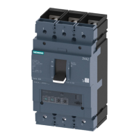
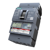
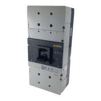
Details the structure and functional principles of 3VF circuit-breakers.

2.2 Technical data

Lists technical specifications for the SIMOCODE-DP and motorized mechanisms.

2.3 Supplementary literature on 3VF communication

Provides references for additional documentation on 3VF communication.

3 3WN6 CIRCUIT-BREAKERS

3.1 Mode of operation and design

Explains the general operational principles of 3WN6 circuit-breakers.

3.2 Bus connection functionality

Describes the capabilities of 3WN6 for bus connection.

3.3 Procedure for connection to communication system

Outlines the step-by-step process for connecting 3WN6 to a system.

3.4 Displaying the data in the 3WN6 circuit-breaker

Details how to access and interpret data from 3WN6 via PROFIBUS-DP.

3.5 Description of software block required for utilizing communication functions with SIMATIC S5 and S7

Explains the necessary software blocks for integrating 3WN6 with SIMATIC.

4 3WN1 and 3WS1 circuit-breakers

4.1 Mode of operation and design

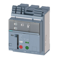
Covers the general operation and design of 3WN1/3WS1 circuit-breakers.

4.2 Functionality and bus connection

Details the functional capabilities and bus connection for 3WN1/3WS1.

4.3 Procedure for connection to communication system

Provides step-by-step instructions for connecting 3WN1/3WS1.

4.4 Special cases

Discusses specific operational scenarios and considerations.

4.5 DP/3WN1, 3WS1 and DP/3WN6 interface modules

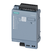
Describes interface modules for 3WN1/3WS1 and 3WN6.

5 APPENDIX

5.1 Reference to PROFIBUS installation guidelines

Points to external PROFIBUS installation documentation.

5.2 Glossary

Provides definitions of technical terms used in the manual.

Related product manuals