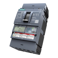
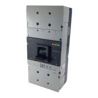
Communication System Manual 3VF, 3WN, 3WS Circuit-Breakers
Copyright Siemens AG 1998. All rights reserved. Version1.0 (05/98)
2
3.5.3.4 Data blocks (DBs) 66
3.5.3.5 Description of examples 69
3.5.3.6 Extract from program listing of supplied example 71
3.5.3.7 Procedure for creating your own project 77
3.5.3.8 Description of visualization with software block 78
3.5.4 STEP 7 program 79
4 3WN1 AND 3WS1 CIRCUIT-BREAKERS 80
4.1 Mode of operation and design 80
4.1.1 General mode of operation 80
4.1.2 Design of the communication-capable 3WN1/3WS1 PROFIBUS system 80
4.1.3 Hardware and software requirements 81
4.2 Functionality and bus connection 81
4.3 Procedure for connection to communication system 82
4.4 Special cases 89
4.5 DP/3WN1, 3WS1 and DP/3WN6 interface modules 89
4.5.1 Device description 89
4.5.1.1 Display/operating elements and interfaces 89
4.5.2 Installation guidelines 90
4.5.2.1 Installing the interface module 90
4.5.2.2 Wiring 92
4.5.2.3 Wiring arrangements, screening and measures to counteract interference voltage 96
4.5.3 Operation 101
4.5.3.1 Operating elements 101
4.5.3.2 Display elements 102
4.5.4 Technical data 103
4.5.4.1 Device data 103
4.5.4.2 Interface data 105
4.5.5 Connecting cables between interface modules and 3WN1/3WS1 106
4.5.6 Displaying data in PROFIBUS-DP 107
4.5.6.1 Parameterization 107
4.5.6.2 Configuration 109
4.5.6.3 Diagnostics 110
4.6 Displaying the data in the 3WN1/3WS1 circuit-breaker 111
5 APPENDIX 113
5.1 Reference to PROFIBUS installation guidelines 113
5.2 Glossary 114
 Loading...

